• The Block Diagram Editor allows users to add comments for each class of block diagram elements.
• The terminals, wires, buses, symbols, and fubs can be described with additional text on the object properties Comment tab.
• The comments appearing on diagrams as well as in the generated HDL code are very helpful while documenting some information or during the analysis of complex designs
2.32 I/O port conversion functions
• Block Diagram will automatically insert conversion function for those pins of a symbol that have a type different than the default type of signals used on a block diagram
• It is possible to manually specify the conversion function for a terminal and connected signal.
• This option allows the use of the user-defined types on block diagrams.
2.33 State Diagram Editor features
• Multiple architectures support
• Code Generation Settings
• Automatic Testbench generation for state diagrams
• HDL code editing
• Asynchronous machines
• Multiple reset support
• Transition Auto Priority
• Junction
• Convert to Hierarchical State
• State register port
• Synthesis Attributes
• Export to previous ASF format
• Report file generation
2.33.1 Multiple architectures support
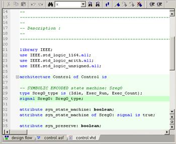
• The State Diagram Editor allows the user to generate the VHDL code that contains an architecture body only.
• In this way you can create and use different implementations (several architectures) for the same entity.
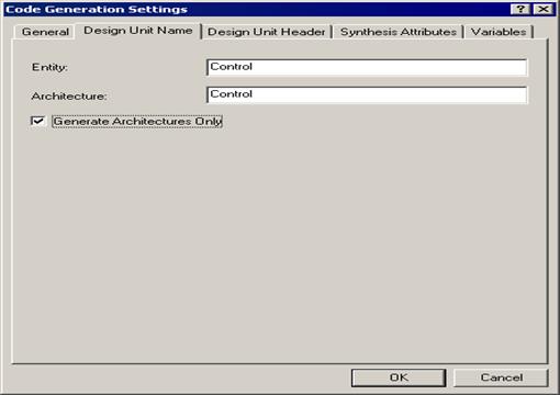
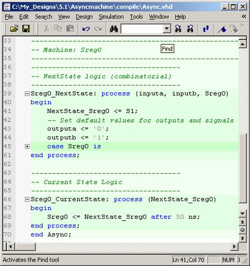
2.33.2 Code Generation Settings
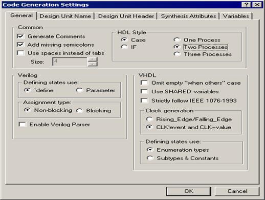
Code Generation Settings dialog:
• To generate a code from a state diagram, you can set several HDL styles.
• You can decide whether to use the if or case statements in the state register description.
• Additionally, you can choose the final form of your state machine logic, that is, whether it will be described by using one, two, or three processes.
• Users can control the header and comments insertion in the generated code.
• The State Diagram Editor allows you to choose the clock specification in the generated code.
• The State Diagram Editor allows designers to use blocking or non-blocking assignments in the generated code.
2.33.3 Automatic Testbench generation for state diagrams
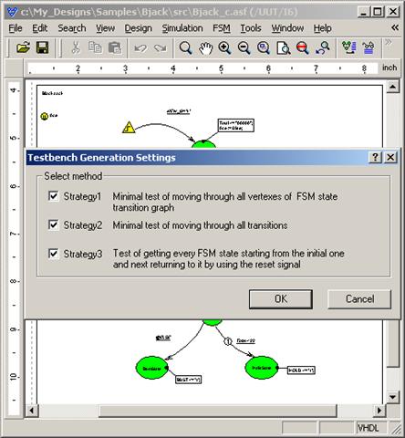
• The State Diagram Editor allows users to automatically prepare testbenches for projects of state machines.
• Users have up to three strategies of testbench testing that can be set individually for specific needs in your projects.
• The purpose of this feature is to speed up the verification process of design units described by means of the state diagram.
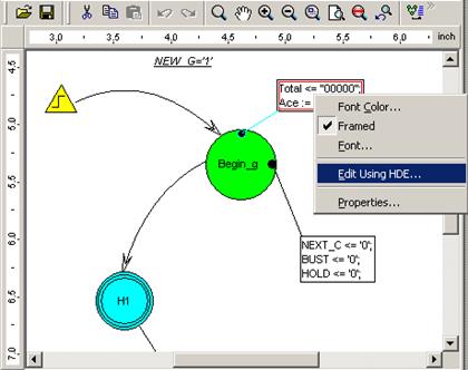
2.33.4 HDL code editing
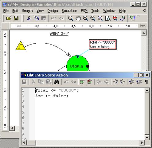
• The Use HDE for Actions editing option has been added to the State Diagram Editor's Preferences.
• It allows users to automatically open the standalone HDL Editor window while editing state actions.
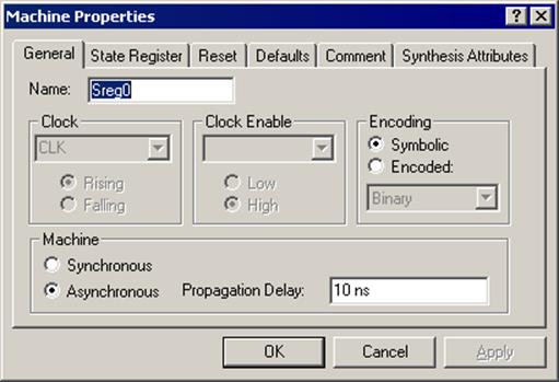
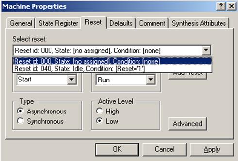
2.33.5 Asynchronous machines
• The State Diagram Editor supports the creation of asynchronous state machines.
• If you create this type of state machine, you can set appropriate options in the Machine Properties window.
2.33.6 Multiple reset support
• The State Diagram Editor allows the user to specify several reset signals in state machine projects.
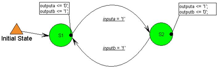
2.33.7 Transition Auto Priority
• The Transition Auto Priority option has been enabled in the State Machine Editor. If several transitions come out of one state, their priorities will be assigned automatically. It allows the user to avoid the ambiguity in the machine's behavior in case two or more conditions are met at the same time.
2.33.8 Junction
• Junction is an additional graphical object that simplifies the creation and analysis of state diagrams.
Уважаемый посетитель!
Чтобы распечатать файл, скачайте его (в формате Word).
Ссылка на скачивание - внизу страницы.