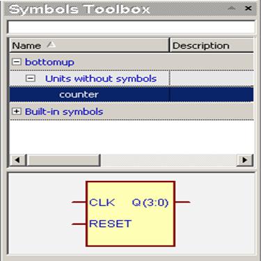
• The Symbol Toolbox contains compiled units without symbols. The symbol is generated ”on-the-fly” when you select the unit you want to use. However, you can add the symbols from other libraries or use Built-in symbols right away.
• Right-click the empty space and select the Select Libraries option from the pop-up menu.
• In the Libraries window, check which libraries you want to use in the current design. Accept the changes by pressing the OK button.
2.8 Creating the Top Level Block Diagram
• Drag the counter symbol to the diagram window and drop it to the right of the Control fub.
•
Use the Wire button to draw the
following connections:
1. from the Clock output port of the Control symbol to the
CLK input of the Counter symbol
2. from the RST output port of the Control symbol to
the Reset input of the Counter symbol
• Hit Esc to return to the Select mode
•
You can rename wires by double-clicking on them
and typing a new name in the Segment box in the Wire Properties
window. Please rename:
- wire drawn in point 1 above to CLOCK
- wire drawn in point 2 above to RST
2.9 Creating the Top Level Block Diagram
• Use the Bus button to draw the following connection, from the Q(3:0) output port of the Counter symbol to the Q(3:0) port of the block diagram
• Hit Esc to return to the Select mode
• You can rename buses by double-clicking on them and typing a new name in the Segment box in the Bus Properties window. Please verify if the bus has the same name and range as the output of the Counter symbol.
2.10 Creating the Top Level Block Diagram
• The completed top_counter block diagram should look like this:
• Please save and close the diagram
• Create the Functional folder, drag top_counter block diagram to the Functional folder in the Design Browser window and reopen it
Note: Symbols placed
on diagrams can contain other block
diagrams, state machines or HDL files.
Design Rule Checking
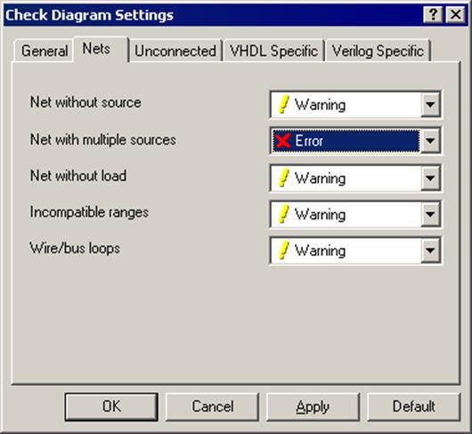
• DRC formally verifies the correctness of connections between symbols on the diagram. Errors are reported in the Console window. You can change the severity level of an error in the Check Diagram Settings window (in the Diagram menu).
• To create tri-state buses you must change the Nets with multiple sources option in the Nets tab.
2.11 Creating Fub Contents
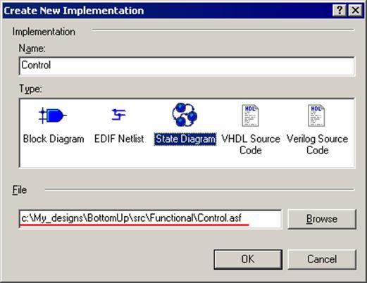
• Right-click on the Control fub in the top level block diagram and select Push
• Click State Diagram in the Type window
• the “Functional\” text should be added automatically before the “Control.asf” in the File box
• Click OK
The Finite State Machine (FSM) editor window should open with an outline of our state machine.
2.12 Creating Fub Contents
Output ports of the machine can be either combinatorial, registered or clocked. Clocked outputs require ”Two Processes” or ”Three Processes” generation pattern. To select between these, right-click the port symbol and select the Properties option from the pop-up menu. You can also change the port type there.
2.13 Creating Fub Contents
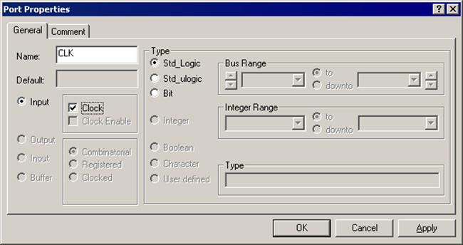
The FSM Editor is designed for behavioral descriptions of State Machines. The Control unit we are going to describe will be synchronous, so we must declare one of the inputs in the diagram as our machine clock.
• Right click on the CLK port symbol in the Control state diagram and select Properties
• Select the Clock checkbox in the Port Properties window
• Click OK
2.14 Creating Fub Contents
• Using the FSM | State menu option or State button in the toolbar, place two states on the diagram as shown in the picture.
• Don’t worry if the state names on your diagram are different from the ones in the picture, we will be changing them anyway.
2.15 Creating Fub Contents
Уважаемый посетитель!
Чтобы распечатать файл, скачайте его (в формате Word).
Ссылка на скачивание - внизу страницы.