• Drag the selected library to the HDL Editor window
• Drop it under the IEEE library clause.
• Repeat this process for IEEE.STD_LOGIC_UNSIGNED.
The counter description should look as follows:
• Compile the design
6.8 Writing a Simple Testbench
• Double-click the Add New File label in the Design Browser
• Choose the Wizards tab and select the VHDL Source Code wizard. This invokes the wizard window.
• Click Next and type Testbench as the name of the file.
• Click Next and then Finish.
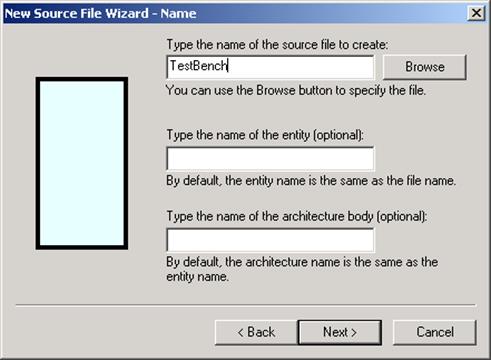
Note: You do not need to specify any ports for the testbench.
6.9 Writing a Simple Testbench
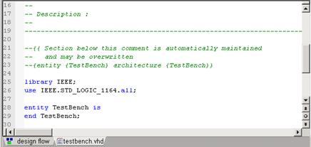
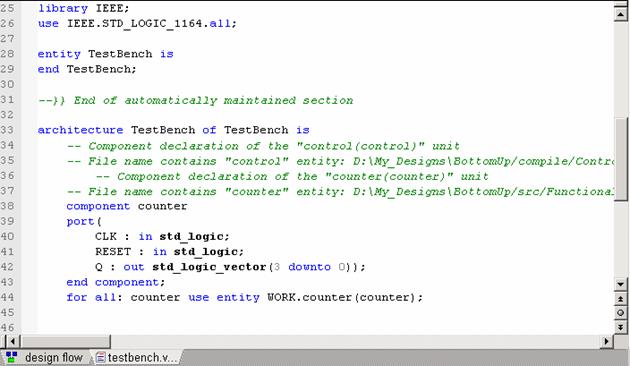
The HDL Editor will open the Testbench file with the following contents.
First, you need to insert the UUT component declaration.
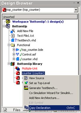
Copy the Counter declaration from the working library.
Use the Ctrl+C keys or select the Copy Declaration option.
Paste the declaration above the begin keyword.
6.10 Writing a Simple Testbench
The Testbench file with the contents should look as follows.
• You will need to create a clocking process to force the UUT model with appropriate pattern.
• You will also need
some signals to bind the testbench with the UUT model.
• Put the UUT: Counter label next to the begin keyword.
6.11 Writing a Simple Testbench
• Type the following line below the Counter component declaration to declare the signals:
signal CLK : std_logic :=‘0’;
signal RESET : std_logic;
signal Q : std_logic_vector(3 downto 0);
• To create a clocking process, you will also need a variable that will stop the simulation. Type the following line below the signal declarations.
shared variable END_SIM : boolean :=FALSE;
• The next step is to map the Counter component with declared signals. Insert the port map below the UUT: counter label.
port map (
CLK => CLK,
RESET => RESET,
Q => Q);
6.12 Writing a Simple Testbench
• Now, you will define the clocking process. Insert the following process description below the port mapping section.
CLK_IN: process
begin
if END_SIM = false then
CLK <= '1'; wait for 10 ns;
CLK <= '0'; wait for 10 ns;
else wait;
end if;
end process;
• You must insert an IEEE library clause at the top of the Testbench description. To do this, use the Language Assistant window as described before but this time, select the IEEE.STD_LOGIC_1164.
6.13 Writing a Simple Testbench
• The Testbench description should look as shown in the figure.
• Now you can apply stimuli for the RESET signal.
6.14 Writing a Simple Testbench
Type the following process description that resets the Counter output at 0ns and stops simulation after 250 ns.
RESET_IN: process
begin
RESET <= '1';
wait for 10 ns;
RESET <= '0';
wait for 250 ns;
END_SIM := TRUE;
end process;
The simulation will stop because the END_SIM value is set to TRUE.
6.15 Writing a Simple Testbench
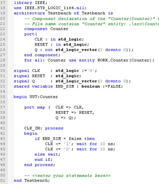
The complete testbench architecture should look as shown in the figure.
6.16 Writing a Simple Testbench
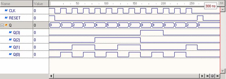
• Compile the Testbench file and set it as a top-level unit. Then simulate it for 300 ns as described in the Course 5- Simulation. The results are shown in the figure.
6.17 Using Testbench Wizard
Active-HDL comes with a Testbench Wizard that automates the process of testbench creation. You can create skeleton testbench files or completely functional testbenches from previously saved waveform files.
To start the wizard, use the Generate Testbench option from the Tools menu.
Уважаемый посетитель!
Чтобы распечатать файл, скачайте его (в формате Word).
Ссылка на скачивание - внизу страницы.