Analysis of pure HDL sources in this form is quite difficult and requires skills
These files can be converted into diagram
F.3 Diagram from HDL
First you will convert bjack.vhd
•
Use the Code2Graphics Conversion Wizard... option
from the Tools menu.
The Code2Graphics application will be invoked
•
Now you can select one of three options:
- Crate a new design…
- Add to current design…
- Do not add to any design…
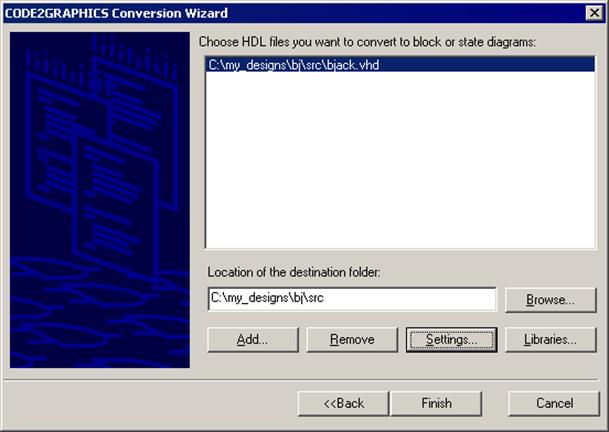
Select second option – this will add created diagram to your design and click Next
 |
F.4 Diagram from HDL
• Press the Add button
• Open the bjack.vhd file
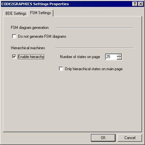
• Press the Settings button
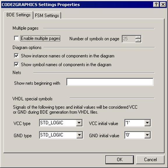
F.5 Diagram from HDL
There are several options:
• Multiple pages – allows to generate multiple pages block diagram
• Diagram options – you are able to set which information about symbols should be visible on diagram
• VHDL special symbols – you are able to set options for generating VCC and GND symbols.
Set options
Press the OK button
F.6 Diagram from HDL
•
Press the Finish button
The following messages will be displayed in the Console Window:
CODE2GRAPHICS: Analyzing file C:\My_designs\bj\src\bjack.vhd ...
CODE2GRAPHICS: Analyze finished successfully.
CODE2GRAPHICS: Analyzing intermediate file C:\...\Temp\bjack.lid ...
CODE2GRAPHICS: Finished successfully.
CODE2GRAPHICS: Updating components according to libraries data ...
CODE2GRAPHICS: Finished successfully.
CODE2GRAPHICS: Generating temporary block diagram file C:\...\Temp\554422.tmp ...
CODE2GRAPHICS: Finished successfully.
CODE2GRAPHICS: Copying temporary bde diagram file C:\...\Temp\554422.tmp into file C:\My_designs\bj\src\bjack.bde
CODE2GRAPHICS: Double click on this line to view the generated log file
F.7 Diagram from HDL
•
Double click on the last line in the Console
window.
The Log file will be opened
F.7 Diagram from HDL
•
Double click on the last line in the Console
window.
The Log file will be opened
F.8 Diagram from HDL
• Open bjack.bde – the block diagram was generated
• Open bjack.bde – the block diagram was generated
F.9 Diagram from HDL
Now you will convert bjack_c
• Use the Code2Graphics Conversion Wizard... option from the Tools menu once more
• Choose to add files to current design again and advance using Next button
 |
F.10 Diagram from HDL
• Press the Add… button
• Open the bjack_c.vhd file
• Press the Settings button
• Switch to the FSM Settings tab. There you can enable hierarchical states generation, which makes a diagram cleaner when you have a lot of states. You can also turn off FSM diagrams generation when you know that all the files are HDL netlists
• Press the OK button
• Press the Finish button
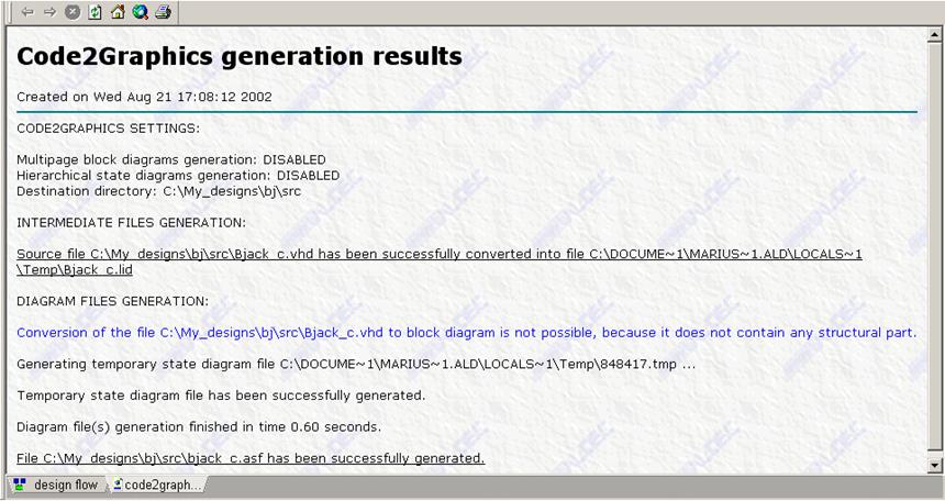
F.11 Diagram from HDL
•
Double click on last line in the Console window.
The Log file will be opened
F.12 Diagram from HDL
• Open bjack_c.asf – the state diagram was generated
Appendix G
State Diagram
G.1 State Diagram
Уважаемый посетитель!
Чтобы распечатать файл, скачайте его (в формате Word).
Ссылка на скачивание - внизу страницы.