• Double click on Signal assignment symbol and type following expression:
EN3 <= EN2 and FULL2;
2.30 Creating the CNT_BCD module
• Please double check your diagram with the picture shown below. CLK and RESET input ports are automatically connected with CLK and RESET counter inputs by global wires.
2.31 Compiling the CNT_BCD module
• Save the created diagram (use Ctrl+S keyboard shortcut or Save button in the toolbar)
• Compile it (press F11 key). The console window will show following messages:
• DRC: Checking file 'c:\my_designs\freq_meter\BCD_COUNTER\src\CNT_BCD.bde'.
• DRC: Warning: CNT_BCD.bde - 0 error(s), 1 warning(s)
• DRC: The results have been written to the log file. Double click on this line to view the log.
• Double click on the last line to open the DRC report file
• Click the link “Unconnected output pins in 'U4'.”
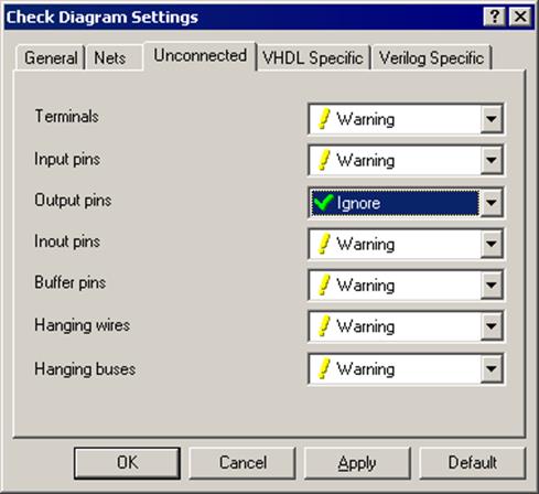
2.32 Customizing the DRC settings
• You will be taken to U4 instance of CNT_4b where an unconnected FULL output exists
• From the Diagram menu, choose Check Diagram Settings
• Switch to Uconnected tab and in combo box for output pins select Ignore
• From the Diagram menu, choose Check Diagram
• If the DRC does not report any problems, close the DRC report
2.33 Creating the CNT_BCD module
• Call context menu for any object on the diagram and use Show in Generated Code
• Generated VHDL code should open with corresponding statements selected
• Close the CNT_BCD diagram and generated HDL code windows
• Please pay attention to AND2 process and signal assignment
3.1 Simulating using the Waveform
• This section will show the following operations:
– How to set top-level design entity
– How to initialize simulation
– How to simulate the tested unit
– How to work with the waveform window
– How to control the simulation run with macro commands
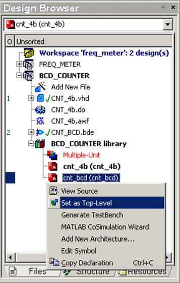
3.2 Top Level Selection
• Set the top-level entity/architecture pair cnt_bcd(cnt_bcd).
• Initialize simulation (Simulation | Initialize menu option).
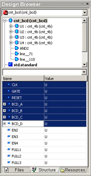
3.3 Using Design Browser
• Go to the Structure tab of Design Browser and click on the root cnt_bcd(cnt_bcd) item
• Select all the counter ports - click on the CLK item, depress the Shift key and click on the BCD_D item
3.4 Adding Signals to Waveform
• Invoke the pop-up menu and choose the Add to Waveform option.
You can also drag & drop them into the waveform window

3.5 Using stimulators
• Select CLK signal on the waveform and invoke its context menu by right clicking on it.
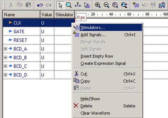
3.6 Clock Stimulator
• Choose the Stimulators option and select Clock stimulator type for CLK signal
• Select 10MHz frequency, 0ps initial delay and 50% duty cycle
• Click on the Apply button
• Choose the Stimulators option and select Clock stimulator type for CLK signal
• Select 10MHz frequency, 0ps initial delay and 50% duty cycle
• Click on the Apply button
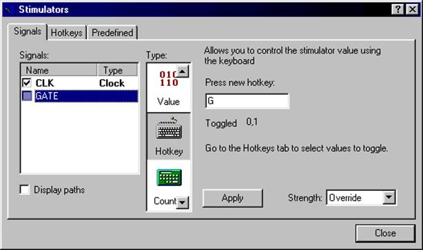
3.7 Hotkey Stimulator
• DO NOT close the Stimulators dialog; in the waveform window select the GATE signal - it will appear in the Signals list of stimulators window
• Select the Hotkey stimulator type; click on the Press new hotkey field and press the G key
• Click on the Apply button
3.8 Formula Stimulator
• Select RESET signal; select the Formula stimulator; enter the following formula: 1 0 ns, 0 100 ns
Уважаемый посетитель!
Чтобы распечатать файл, скачайте его (в формате Word).
Ссылка на скачивание - внизу страницы.