2.18 Creating the CNT_BCD module
• Use the Hide Docked Window
button located in the upper right corner of the main window to
enlarge the Block Diagram Editor window.
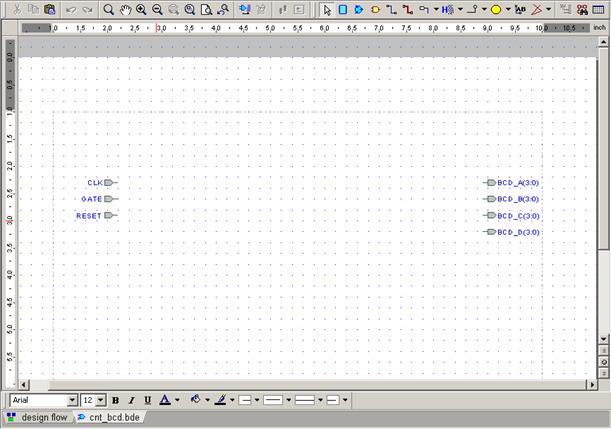
The window should look like the picture below:
2.19 Creating the CNT_BCD module
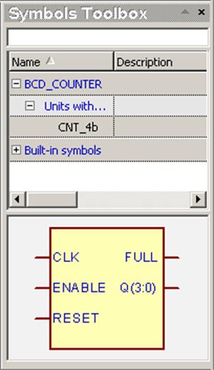
• Click the Show Symbol Toolbox
button ![]()
on the Block Diagram Editor toolbar, then click CNT_4b on the list. The
preview of the symbol for the previously compiled CNT_4b.vhd file will be
displayed at the bottom of the toolbox.
• If you do not see any symbols listed, please click the small plus sign by the library name to expand library contents
• You can add libraries to the toolbox by
right-clicking inside and selecting Choose Libraries from the shortcut
menu
Note: symbols that were never used in the diagram are displayed in the
special subgroup named Units without symbols
2.20 Creating the CNT_BCD module
• Drag the cnt_4b symbol from the toolbox to the diagram area four times; afterwards, the diagram should look as follows:

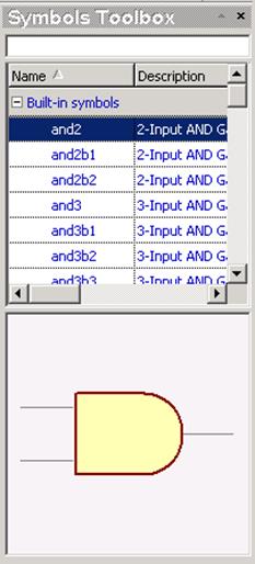
• Click the and2 symbol on the list in the Symbol Toolbox. It is located in the Built-in symbols subgroup. Then drag it once to the block diagram area
2.21 Creating the CNT_BCD module
• After placing 4 instances of the cnt_4b symbol and one instance of the and2 Built-in symbol, you can close the Symbol Toolbox and proceed to inserting a VHDL process and a signal assignment
2.22 Creating the CNT_BCD module
• Place a process symbol in the block diagram – you can find option “Process” in menu Diagram | VHDL
• Place a signal assignment symbol in the block diagram – you can find option “Signal Assignments” in menu Diagram | VHDL
2.23 Creating the CNT_BCD module
• Use the Bus button ![]() to connect counter outputs with output
terminals
to connect counter outputs with output
terminals
2.24 Creating the CNT_BCD module
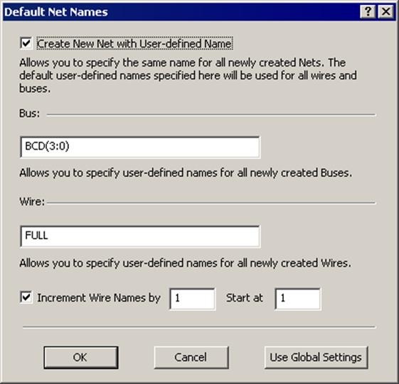
• From the Diagram menu, choose the Default Net Names
• Select the Create New Net with User-defined Name checkbox
• In the edit box for buses specify BCD(3:0)
• In the edit box for wires specify FULL
• Choose to increment wire names by 1 starting at 1
2.25 Creating the CNT_BCD module
• Use the Wire button ![]() to draw connections between Full outputs
and Process, Signal Assignment and Built-in primitive. The diagram should look
like shown in the picture below
to draw connections between Full outputs
and Process, Signal Assignment and Built-in primitive. The diagram should look
like shown in the picture below
2.26 Creating the CNT_BCD module
• Similar way draw connections between the Process, Signal Assignment and Built-in primitive output to the Enable inputs. The wires should be called EN2, EN3 and EN4.
2.27 Creating the CNT_BCD module
• Use the Global Wire button  to place yellow circles to the right of the
CLK and RESET input terminals.
to place yellow circles to the right of the
CLK and RESET input terminals.
• Double click on the circle placed by the CLK port and enter CLK in the Net Name field in the Global Wire Properties window, then click OK.
• Double click on the circle placed by the RESET port and enter RESET in the Net Name field in the Global Wire Properties window, then click OK.
• Completed global wire definitions should look like this:
2.28 Creating the CNT_BCD module
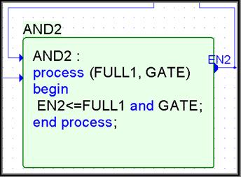
• From the context menu for Process_1, “Properties” option. Change its name to AND2
• Make process contents visible by choosing “Show text” option
• Select the Save text in external file and specify AND2.vhd as file name
• Verify the Sensitivity List
• Double click on process module and type process contents

2.29 Creating the CNT_BCD module
Уважаемый посетитель!
Чтобы распечатать файл, скачайте его (в формате Word).
Ссылка на скачивание - внизу страницы.