Port Out1: Cast = unsign, Number of Bits = 31, Fractional Part = 24, Quantization = truncate, Overflow = saturate
NOTE:
Please use in all symbols “Add signals to Waveform” option
This item finish task with Co-Simulation Wizard for Simulink
All required parameters and MATLAB design has been finished
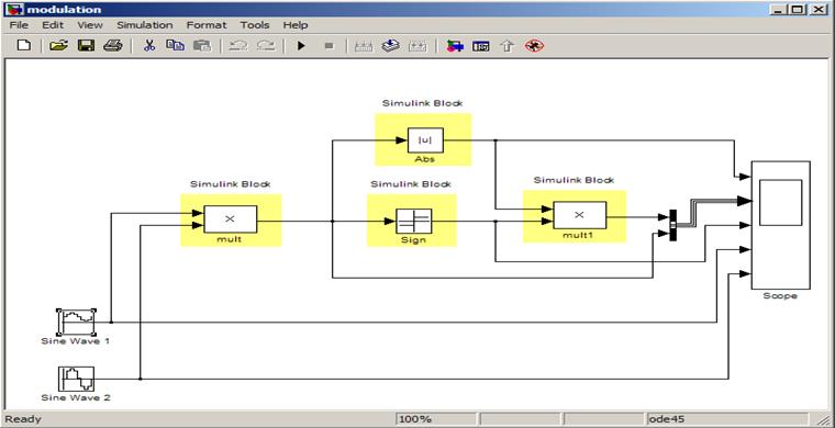
13.17 Design Example
- MATLAB simulation model
1. Please start MATLAB
2. Set Path to the Output Directory.
Please note that it is Output Directory defined inside the Co-Simulation Wizard for Simulink.
3. Please start Simulink from the MATLAB toolbar
4. Choose Open and open Modulator.mdl file stored inside the Active-HDL
example design Modulator.
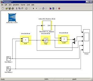
Then you will have MATLAB Simulation model as displayed in this slide
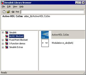
13.18 Design Example
- create co-simulation model
Inside Modulator.mdl please replace MATLAB Abs with m_abs symbol
from the ALDEC Blockset library.
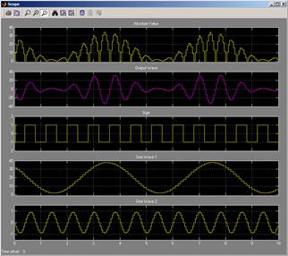
13.19 Design Example
- simulation
Please run simulation using Start Simulation button from the Simulink toolbar.
Simulation can be stopped using Stop Simulation button from the Simulink toolbar.
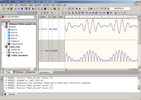
13.20 Design Example
- waveform settings
Active-HDL waveform can display signal values in analog shape.
Please use inside the waveform signal properties to define display parameters for
m_abs symbol ports.
Please set paramaters:
• Signal In1: Radix - decimal, Notation - Signed 2`s Complement, Display - Analog, Height - 128
• Signal Out1: Radix - decimal, Notation - Unsigned, Display - Analog, Height - 128
Active-HDL Interfaces
Celoxica C-Synthesis Flow
Course 14
Outline
With the growing complexity of today's designs, the methodology of a hardware description is changing and it forces designers to search for new solutions, design tools, or even description languages that could be used to specify the behavior of digital devices.
The Active-HDL's Design Flow Manager provides a flowchart and interface to Celoxica's Handel-C-to-hardware DK Design Suite. Introducing the flowchart allows the DK Design Suite users to run the tool directly from Active-HDL and "translate" their Handel-C-based designs to VHDL, Verilog, or EDIF that can be then verified in the integrated simulation environment.
This training will help you get familiar with the Celoxica flowchart and show you how to use it in Active-HDL.
14.1 Requirements
1. Active-HDL with support of Handel- C
2. Celoxica DK2 suite
3. Synthesis tool for example: Synplify, Exempar Leonardo, Synopsys FPGA Compiler
4. An implementation tool : Xilinx Implementation Tool, Altera Implementation Tool
14.2 Active-HDL new Design
1. Start Active-HDL
2. Create new Active-HDL workspace
3. Create new design
4. Add the following source files from Celoxica installation using Add file
to design option
Please use files listed below:
(<DK_Design_Suite_directory>\examples\vhdl\example3) :
- receiver.hcc
- filter.vhd
- wrapper.vhd
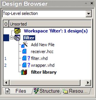
14.2 Active-HDL new Design
Your workspace and design should look like as displayed below
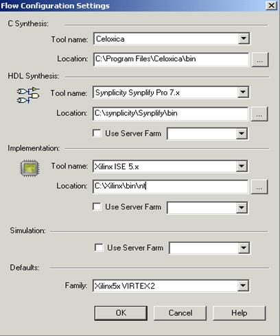
14.3 Setting options for Celoxica Flowchart
Go to Design menu and select Flow Setting
Please choose required tools from as displayed below
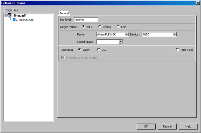
14.4 C Synthesis Settings
Before you run Celoxica, you need to specify the C-synthesis settings.
To do so, press the Celoxica's Options button in the Design Flow window.
In the Celoxica Options window, specify the top-level unit,
target format, family, device, and speed grade.
14.5 C synthesis
Now, you have specified in Active-HDL all the settings required to run C-synthesis with the Celoxica's environment. You have two choices either to run the synthesis in Batch mode or invoke the Celoxica DK Suite’s GUI.When GUI mode is selected, pressing the Synthesis button in the Design Flow window starts DK Design Suite and loads the Example3 sample design. The design contains only one source file - receiver.hcc.
Уважаемый посетитель!
Чтобы распечатать файл, скачайте его (в формате Word).
Ссылка на скачивание - внизу страницы.