2. Expand a source file (e.g. abs.vhd) that contains a design unit that will be used as a black-box.
3. Right-click this unit (e.g. m_abs(beh)) and choose the Co-Simulation Wizard for Simulink option or choose the Co-Simulation Wizard for Simulink option from the Tools menu
This step can be done by using the Co-Simulation Wizard for Simulink.
To run the Co-Simulation Wizard for Simulink in Active-HDL:
1. Open the Active-HDL design that contains units to be co-simulated and compile sources.
2. Expand a source file (e.g. abs.vhd) that contains a design unit that will be used as a black-box.
3. Right-click this unit (e.g. m_abs(beh)) and choose the Co-Simulation Wizard for Simulink option or choose the Co-Simulation Wizard for Simulink option from the Tools menu
13.3 Using Co-Simulation Wizard for Simulink
- interface signals
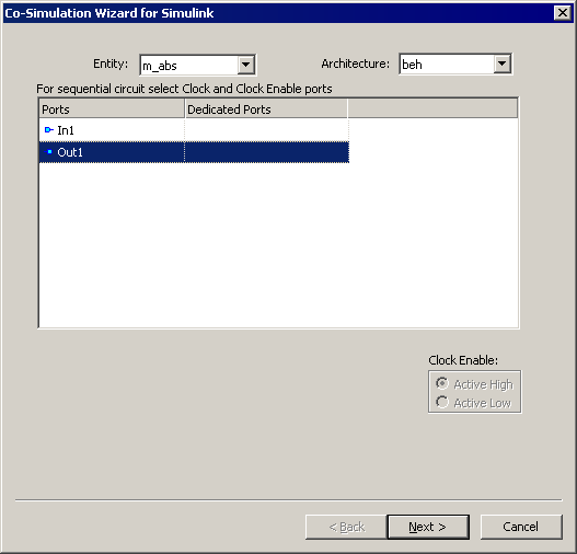
The Co-Simulation Wizard for Simulink dialog box opens.
The first Wizard's window displays all interface signals of the unit.
13.4 Using Co-Simulation Wizard for Simulink
- interface signals
1. Entity/Module
Allows you to select an entity or module to be co-simulated. You can select
an entity/architecture pair or module that you want to co-simulate (black-box)
from the pop-up menu in the Design Browser window or you can choose the Co-Simulation Wizard for Simulink option from the Tools menu.
2. Architecture
Allows you to select an architecture associated to the entity specified in the Entity
list box.
3. Dedicated ports
This column lets you specify the ‘special’ interface signals – clock and clock enable inputs.
4. Clock Enable
Specifies the active level of the Clock Enable signal.
13.5 Using Co-Simulation Wizard for Simulink
- interface signals customization
13.6 Using Co-Simulation Wizard for Simulink
- interface signals customization
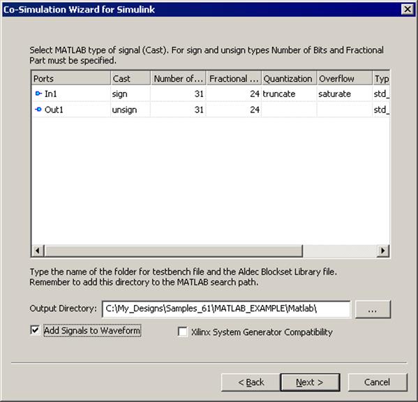
1. Ports
Lists all ports of the simulated unit.
If you have specified the clock (CLK) and clock enable (CE) signals in the first window, these ports are not displayed in the Ports column.
2. Cast
Specifies the numerical representation of a signal's value.
Available types are:Boolean for scalars, SIGN (2's Complement) and UNSIGN for vectors.
3. Number of Bits
Specifies the width of the selected signal.
4. Fractional
Part
Specifies how many bits are available to the right side of the binary point
(i.e. the size of the fraction). The binary point position must fit between
zero and the number of bits specified in the Number of Bits column.
5. Quantization
Specifies the type of quantization method (available values are: truncate,
round ).
6. Overflow
Specifies handling method of arithmetical overflow (available values are: saturate,
wrap, error).
7. Type
Displays the type of the signal.
Supported VHDL types are: BIT, BIT_VECTOR, STD_ULOGIC, STD_ULOGIC_VECTOR, STD_LOGIC, STD_LOGIC_VECTOR.
8. Add signals
to waveform
If this option is checked then interface signals selected in the last wizard
window will be added to the waveform editor during simulation.
9. Xilinx System Generator Compatibility
Enables automatic generation of the unit that will be compatible with Xilinx System Generator.
13.7 Using MATLAB CoSimulation Wizard
- ALDEC Blockset library
The Co-Simulation Wizard for Simulink creates the ALDEC Blockset library, common for all Active-HDL designs in current workspace.
This library can be found in MATLAB's Simulink Library Browser
NOTE:
Output
Directory
Specifies the directory (by default, \$WSP\Matlab) where the output
files are created by the Wizard. This directory also stores files describing a
library (slblocks.m and aldec_lib.mdl) and containing information
on black-boxes that are to be simulated in the MATLAB environment.
13.8 Simulation with MATLAB
Active-HDL Design Output Directory selection inside MATLAB.
1. Start MATLAB.
2. Choose the Set Path option
form the File menu.
This option allows you to specify the
Уважаемый посетитель!
Чтобы распечатать файл, скачайте его (в формате Word).
Ссылка на скачивание - внизу страницы.