• Modify or delete existing aliases and their value mappings
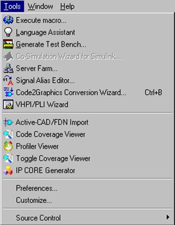
5.53 Signal Alias Editor
Creating Aliases
Choose the Signal Alias Editor option from the Tools menu.
Create aliases for 8051 instructions and save them to a file using Save As toolbar button.
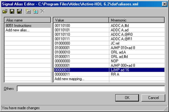
5.54 Signal Alias Editor
Using Aliases
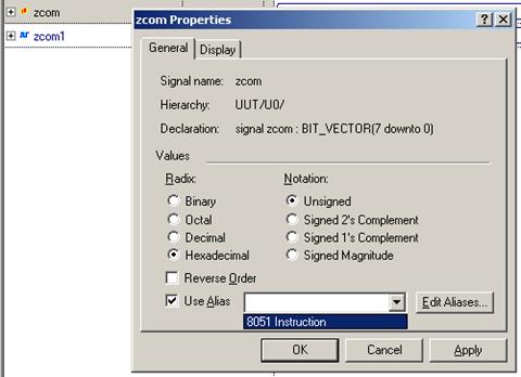
• You can choose the Use Alias option in the signal’s Properties window
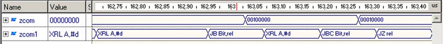
• In the waveform, you will see aliases previously mapped to each value of the signal
Design Verification
Creating Testbenches
Course 6
6. Testbench
HDL testbenches are HDL programs that describe simulation input by using standard HDL language procedures.
Simply speaking, a testbench is a top-level hierarchical model that instantiates the Unit Under Test (UUT) and drives it with a set of test vectors as well as compares generated results with expected responses.
A typical HDL testbench is composed of three main elements:
– Stimulus Generator - driving the UUT with certain signal conditions (correct and incorrect transactions, minimum and maximum delays, fault conditions, etc.).
– Unit Under Test (UUT) - representing the model undergoing verification.
– Verifier - automatically checks and reports any errors encountered during simulation. It also compares model responses with expected results.
6.2 Testbench Types - Off-line Configuration
In Off-line configuration, the Stimulus Generator and the Verifier read all data (test vectors, expected results) from the previously saved files. The Stimulus Generator reads all input signals from a file and provides clock processes. The Verifier compares the UUT responses with the expected results and reports any faulty behavior.
6.3 Testbench Types - On-line Configuration
The Stimulus Generator provides the same input signals to each tested model. Thus, the response of all models are simultaneously generated without any user interaction such as exchanging the components. The Verifier operation is much simpler than in the off-line configuration because it only gathers simulation results from each model and compares them, detecting any differences and deciding whether to continue a simulation or not.
6.4 Testbench Types - Adaptive Configuration
The Stimulus Generator uses high-level abstraction techniques to adapt test vectors to the changing conditions and responses of a tested model. As a result, test vectors are generated in response to feedback from the UUT and the Verifier.
6.5 Testbench Example
architecture TESTBENCH_ARCH of testbench is
component GENERATOR is
port( A : in STD_LOGIC;
B : in STD_LOGIC;
CLOCK : in STD_LOGIC;
RESET : in STD_LOGIC;
Y : out STD_LOGIC);
end component;
shared variable end_sim : BOOLEAN := false;
signal RESET,Y : STD_LOGIC;
signal A,B,CLOCK : STD_LOGIC;
begin UUT: GENERATOR
port map( A => A,
B => B,
CLOCK => CLOCK,
RESET => RESET,
Y = >Y);
. . .
CLK_IN: process
begin
if end_sim = false then
CLOCK <= '0'; wait for 10 ns;
CLOCK <= ’1'; wait for 10 ns;
else wait;
end if;
end process;
.
.
.
end_sim := true;
wait;
end process;
end TESTBENCH_ARCH;
6.6 Writing a Simple Testbench
We will create a simple testbench file for the counter created in the Course 2 – Bottom-Up Design Methodology.
Before we start, you must add a library clause to the counter.vhd file.
• Open the design
• Double-click the
counter.vhd file
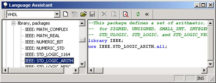
• Open the
Language
Assistant window
• Select the Language templates | Library packages branch
• Select the IEEE:STD_LOGIC_ARITH library.
• 6.7 Writing a Simple Testbench
6.7 Writing a Simple Testbench
Уважаемый посетитель!
Чтобы распечатать файл, скачайте его (в формате Word).
Ссылка на скачивание - внизу страницы.