Active-HDL State Diagram allows you to create parallel state machines
Open the sample design Lights
There is a testbench for a state machine that needs to be created.
G.2 State Diagram
The machine should have two modes of operation:
• In the first mode, only yellow light is blinking.
• In second mode, lights are changing in order: yellow, red, red and yellow simultaneously then green.The first state machine is responsible for changing the mode of operation and the second one is responsible for turning on and turning off appropriate lights.
G.3 State Diagram
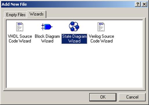
• Double click on Add new file… in the Design Browser
• Switch to the Wizard tab
• Select State Diagram Wizard
• Press the OK button
G.4 State Diagram
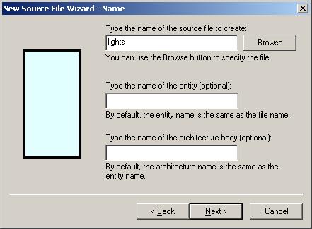
• Press the Next button
• Select VHDL for the language to be generated
• Press the Next button
• Type lights as file name
• Press the Next button
G.5 State Diagram
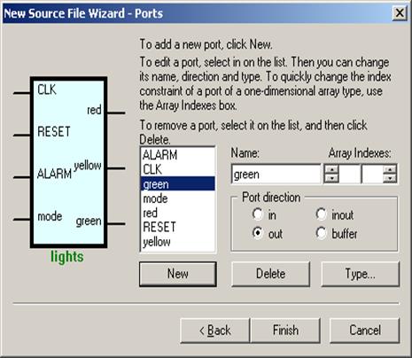
•
Add input ports:
- CLK
- RESET
- ALARM
- mode
•
Add output ports:
- red
- yellow
- green
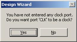
• Press the Finish button
• Press the Yes button to accept proposed clock signal
G.6 State Diagram
A new State Diagram will be created with interface signals
symbols on it.
• Select the frame below the ports symbols
• Right click on it and select the Properties option
• Change the name to control – it will be the name of the first machine

G.7 State Diagram
Use the bottom handle to resize the state machine frame like show in the picture.
G.8 State Diagram
•
Press the State ![]() icon on the
toolbar
icon on the
toolbar
• Place two states on block diagram
• Hit the Esc key
G.9 State Diagram
• Right click on the first state
• Select Properties
• Change the name to STOP
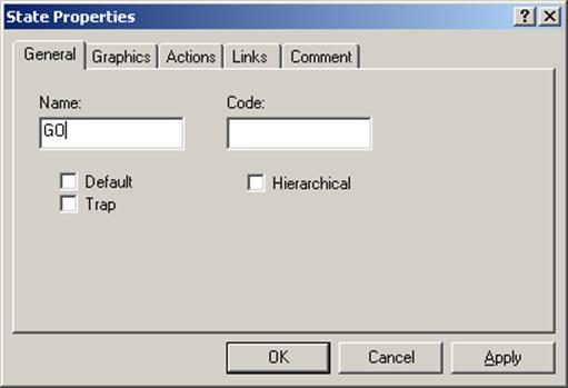
• Change the name of the second state to GO
G.10 State Diagram
Now you will define reset
• Right click inside the frame
• Select Properties
• Switch to the Reset tab
• Click “Add Reset” button
• Select RESET as Name
• Select STOP as State
• Select Asynchronous as Type
• Select High as Active Level
•
Press the OK button
The Reset symbol ![]() will appear on diagram
will appear on diagram
 |
G.11 State Diagram
Now you will define transitions
•
Press the Transition  icon on the
toolbar
icon on the
toolbar
• Draw transitions from from STOP to GO and from GO to STOP
G.12 State Diagram
Now you will define conditions
•
Press the Condition  icon on the
toolbar
icon on the
toolbar
• Click on the transition from STOP to GO and type condition mode = ‘1’
• Click on the transition from GO to STOP and type condition mode = ‘0’
G.13 State Diagram
Now you will create the second machine
• Open the FSM menu
•
Select the New Machine option
A new machine frame will be created in the free space of the page
•
Change the name
of the second machine
to action
G.14 State Diagram
• Put two states on the second machine
• Change their names to NOPE and LIGHT
• Draw transitions between these states
Уважаемый посетитель!
Чтобы распечатать файл, скачайте его (в формате Word).
Ссылка на скачивание - внизу страницы.