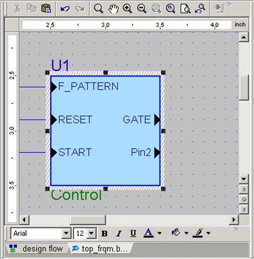
• Double-click Pin2 and change
its name to END_RESET
• Click outside the FUB and
answer Yes when asked if you
want to save changes
to the fub
6.6 Creating the top level Block Diagram
• The completed fub should look 
like this:
(we will fill the fub contents
after completing our top level
block diagram)
• We can proceed now to placing the remaining
symbols on the top_frqm block diagram:
- one instance of the CNT_BCD module
- four instances of the HEX2LED module
(use Show Symbol Toolbox button and drag symbols from the toolbox to the
diagram; if necessary add the BCD_COUNTER library using context menu in Symbol
Toolbox)
6.7 Creating the top level Block Diagram
• The diagram with all six symbols placed should look like this:
6.8 Creating the top level Block Diagram
• Use the Wire button ![]() to draw the following connections:
to draw the following connections:
1. from the F_INPUT input port to the CLK input of
the CNT_BCD symbol
2. from the GATE output of the CONTROL symbol to
the GATE input of the CNT_BCD symbol
3. from the END_RESET output of the CONTROL symbol to
the RESET input of the CNT_BCD symbol
• Hit Esc to return to the Select mode
• You can rename wires by double-clicking on
them and typing a new name in the Segment box in the Wire Properties
window. Please rename:
- wire drawn in point 2 above to GATE
- wire drawn in point 3 above to END_RESET
6.9 Creating the top level Block Diagram
• Use the Bus button ![]() to draw the following connections:
to draw the following connections:
1. From: LED_A, LED_B, LED_C and LED_D
output port symbols
To: LED_x
outputs – U3, U4, U5 & U6 instances, respectively
2. From: BCD_A, BCD_B, BCD_C and
BCD_D outputs of
the CNT_BCD symbol
To: HEX_x inputs – U3, U4, U5 & U6 instances of HEX2LED, respectively
• Hit Esc to return to the Select mode
• You can rename buses by double-clicking on them and typing a new name in the Segment box in the Bus Properties window. Please rename buses drawn in point 2 so that they have the same names and ranges as the outputs of the CNT_BCD symbol.
6.10 Creating the top level Block Diagram
• The completed Top_frqm block diagram should look like this:
• Please save the diagram, close it, drag it to the Functional folder in the Design Browser and reopen it
7.1Creating a State Diagram
• Please right-click on the CONTROL fub in the top level block diagram and select Push
• Click State Diagram in the Type: box
• Click OK
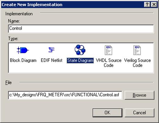
The FSM Editor window should open with an outline of our state machine.
7.2 Creating a State Diagram
The FSM Editor is designed for behavioral description State Machines, we need to declare one of the inputs in the CONTROL diagram as our machine clock.
• Right click on the F_PATTERN port symbol in the CONTROL state diagram and select Properties
• Select the Clock checkbox in the Port Properties window
• Click OK
Using the Properties option for the END_RESET and GATE outputs, double check if both are Registered.
7.3 Creating a State Diagram
• Using the FSM | State menu option or
State button ![]() in the toolbar place
three states on the diagram, as shown in the picture.
in the toolbar place
three states on the diagram, as shown in the picture.
7.4 Creating a State Diagram
You can change a state name by right-clicking on the state, selecting Properties and typing a new name in the General tab of the State Properties window. If you are zoomed close enough, you can double click the old name and type the new name directly in the diagram.
Уважаемый посетитель!
Чтобы распечатать файл, скачайте его (в формате Word).
Ссылка на скачивание - внизу страницы.