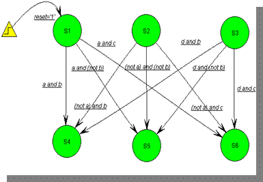
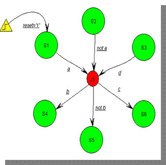
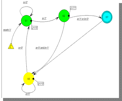
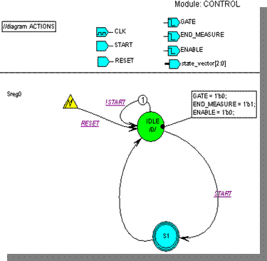
• Junction is a "connector" that enables a set of transitions to be replaced by another reduced set of state-to-state transitions.
• The less transitions on a state diagram, the easier its evaluation is.
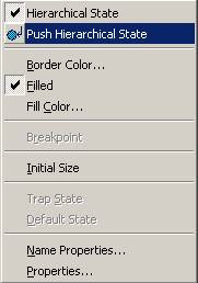
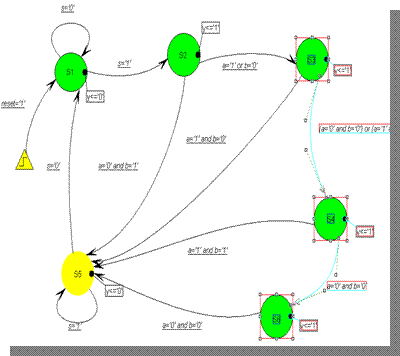
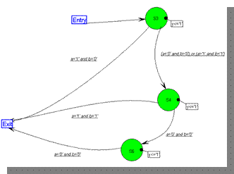
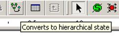
2.33.9 Convert to Hierarchical State
• After a part of the state diagram has been selected, it can be converted to a Hierarchical State. If you work on very complex state machine projects, you can use Convert to Hierarchical State option to decompose your machine and make the results easier to document and analyze for you or other designers.
2.33.10 State register port
Contents of the state register can be passed to a combinatorial output vector. This is useful when creating Full Moore machines and for debugging purposes as well.

2.33.11 Synthesis attributes
Synthesis attributes can be added to the generated HDL code to better control and improve FSM synthesis results.
• Enable Synthesis Attributes and choose the tool you would like to use for syntesis in Code Generation Settings
• Select the appropriate values for attributes supported by your synthesis tool.


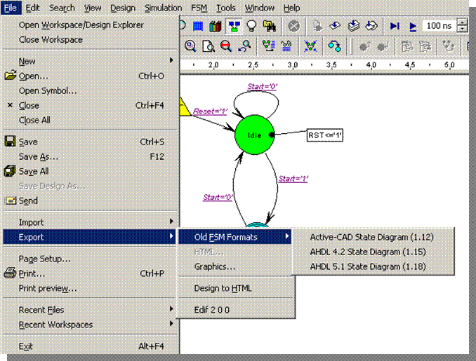
2.33.12 Export to previous ASF format
As new features were introduced in the Finite State Machine Editor, file formats had to evolve.
For backwards compatibility, the FSM Editor provides Export to old file formats option available in File menu.
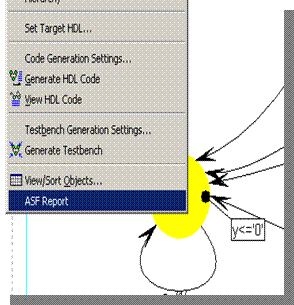
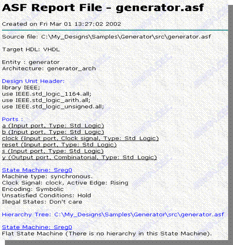
2.33.13 Report file generation
• The State Diagram Editor generates the documentation for a state machine project.
• The ASF Report is an auxiliary tool that gathers complete information about the created state machine.
• It contains details of port types, structure of the design hierarchy tree, specified reset signal(s) and active clock's edge, headers, etc.
3. Design Entry & Management
Design Management
Course 3
3. Efficient Design Management
• Set up Designs Using Wizards in Design Browser
• Archive Designs
• Create Revisions
• Use Library Manager:
• Browse Libraries
• Add New Libraries
• Update Existing Libraries
• Create Macro Command Files
• Use Tcl/Tk, Perl and VBasic Scripts
• Add External Tools to Active-HDL
• Plug in IP Cores
• Using Source Control
3.1 Creating New Design
The design creation process based on Design Wizards is very similar in every case, whether it uses HDL code, State Machines, or Block Diagrams.
• To set up a new design, select the New design option in the File menu.
• In the New Design Wizard window, you can choose the design entry method:
– To add existing files, check the Add existing resource files option. Select the source files in the Open window and finish the design creation by clicking the Finish button.
– To import a design from Active-CAD, check the Import a design from Active-CAD option.
– To create an empty design, check the Create an empty design option.
• Create an empty design.
See Course 1 and 2 for more details on Wizards
3.2 Using Design Browser
The Design Browser is a tool designed for managing the attached design resources.
• Add, remove, view, modify, or perform another specific operation on a resource file.
• View the contents of the default working library of the current design.
• View the elaborated structure of the currently simulated design unit.
• View objects defined within specific regions of the currently simulated design unit.

3.3 Using Design Browser
The Design Browser window includes three tabs:
• The Files tab shows resource files attached to the design and displays the contents of the default working library.
Уважаемый посетитель!
Чтобы распечатать файл, скачайте его (в формате Word).
Ссылка на скачивание - внизу страницы.