5.4 Adding Signals
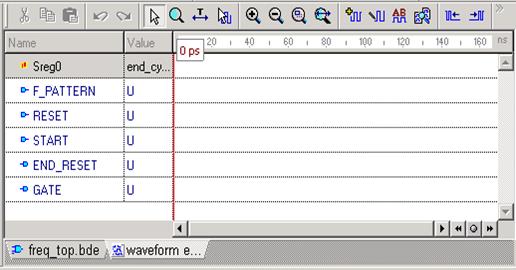
To see the results of simulation, you must add the signals to the Waveform Editor window. You can either drag them from the Design Browser window or use the Add signals window.
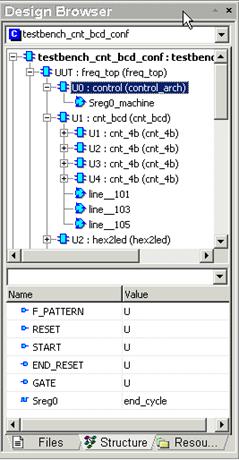
• In the Design Browser window, switch to the Structure tab and select a particular component or click the Root structure to see all design signals.
• Select the signals and drag them to the Waveform Editor window
5.5 Adding Signals
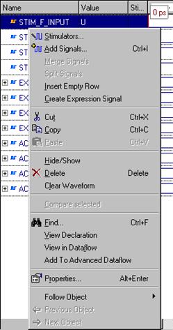
To add signals using the Add Signals window, click the toolbar icon or select the Add Signals option from the pop-up menu.
• Select a component from the design structure
• Select the signals
• Click the Add button
• Close the window
by clicking the
Close button
Note: You can add signals individually by selecting their names and clicking the Add button.
5.6 Adding Signals
You can also drag a component from the Design Browser window to add all of its signals to the Waveform Editor window.
• Select any component and drag it
to the Waveform Editor. Notice that all
the signals are automatically added.
5.6 Ref.A Removing Signals
To remove the signal from the Waveform Editor, select the signal name and press the Delete key or choose the Delete option from the pop-up menu.
• Select any signal and press the Del keyboard key. This signal should be removed from the current waveform window.
5.7 Initializing Simulation
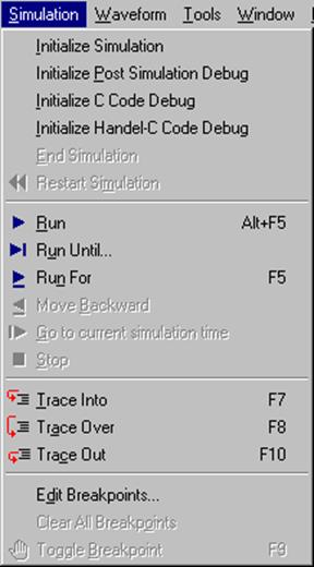
The Initialize Simulation command in the Simulation menu launches elaboration and initialization of the simulation model.
During elaboration, the simulator loads design entities and builds the simulation model in the computer memory. During initialization, all objects in the model (signals, variables, etc.) acquire their initial values (either default or explicitly specified) and all concurrent processes are executed once until their suspension.
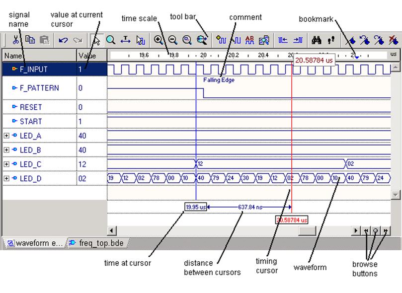
5.8 Initializing Simulation
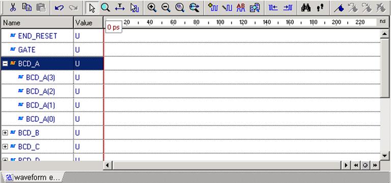
Notice that the + sign appeared to the left of some signals. You can click the + sign to expand the view. This is the way Waveform Editor handles complex signals like buses.
After you have added the signals, you need to force them with specific values to see the model’s response.
5.9 Stimuli
Active-HDL supports the following methods of stimulating or forcing input signals during the simulation:
– Manually selected stimulators from the Active-HDL resources
– HDL Testbench files – see Course 6 Testbench for details
– Simulation commands entered in the Console window
– Files containing simulation macro commands
– Test Vector files imported from Active-CAD
– Simulation input based on waveforms edited by the user
5.10 Stimulators
For the purpose of this course, we will use stimulators to drive the model with its required stimuli.
Stimulators are specialized signal waveform generators that can produce any desired legal value on the model’s inputs. There are several types of stimulators:
• Clock
• Formula
• Value
• Hotkey
• Counter
• Predefined
• Custom
• Random
5.11 Stimulator types
• Clock drives a signal with a clock pulse wave.
• Counter drives a signal with a sequence of values that represent consecutive states of a counter.
• Custom drives a signal with its own waveform existing in the Waveform Editor window.
• Formula drives a signal with values defines by a formula expression.
• Hotkey drives a signal with values toggled with a specific hotkey.
• Predefined specifies that the signal is to be driven with a named stimulator whose definition is on the Predefined tab.
• Value drives a signal with a constant value.
• Random drives a signal with a sequence of integer values distributed according to standard probabilistic functions.
5.12 Assigning Stimulators
To assign a stimulator to a signal, select its name in the Waveform Editor window and click the toolbar button. This invokes the Stimulators window.
Уважаемый посетитель!
Чтобы распечатать файл, скачайте его (в формате Word).
Ссылка на скачивание - внизу страницы.