• Compile the top level block diagram (top_frqm.bde)
• Select top_frqm(top_frqm) entity/architecture pair as your top level
Your design is ready for final testing.
8.1 Simulating the Top Level
Before starting simulation, we will learn how to create waveforms manually and then use them for simulation.
NOTE: Do not initialize simulation during waveform creation.
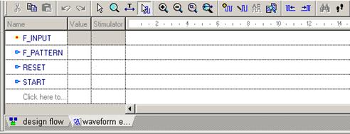
• Open the new Waveform Viewer
window ![]()
• Click Edit Mode button![]()
• Double click “Click here to add new
signal” text and type F_INPUT
• Hit Enter or click outside the signal name area
• Repeat the same steps to add F_PATTERN, RESET and START signal names
8.2 Simulating the Top Level
• You may be requested to initialize simulation, if you have set the simulation top-level
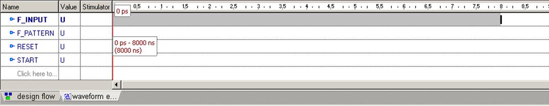
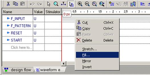
• Mark a block in the F_INPUT row by dragging the mouse from the 8000 ns point to the 0 ns point (it is easier than to start block selection from 0)
• Right-click inside the block and
select Fill from the shortcut
menu
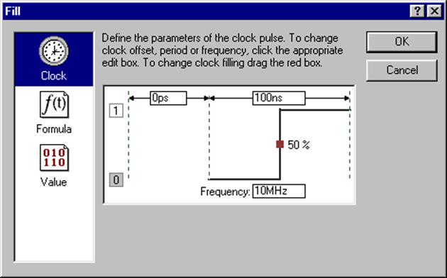
8.3 Simulating the Top Level
• Fill the marked block
with 10MHz clock
(no offset, initial
value 0, 50% duty cycle)
• Click OK
• Mark 0 ns- 8000 ns block in the F_PATTERN
row and fill it with
500kHz clock (no offset, initial value ‘0’, 50% duty cycle)
8.4 Simulating the Top Level
• Mark another block, this time starting at the 8000 ns point in the RESET signal row and ending at the 0 ns point in the START row (you are marking block two signal rows wide and 8000 ns long)
• While the block is selected, hit the ‘0’ button on your keyboard: the whole block will be filled with logical ‘0’
• Mark 0 ns - 1000 ns block in the RESET signal row and fill it with logical ‘1’
• Mark 2000 ns - 6500 ns block in the START signal row and fill it with logical ‘1’
NOTE: If you made a mistake and signal edges do not fall into the places listed above, you can drag signal edges to the desired positions
8.5 Simulating the Top Level
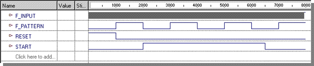
• The complete waveform should look like in the picture above
• When all operations are completed, click
the Select Mode button ( ![]() ) to leave the Edit mode
) to leave the Edit mode
8.6 Simulating the Top Level
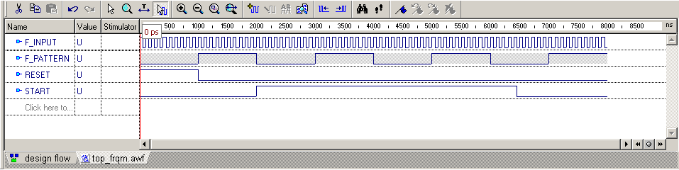
• Your waveform should now look as in this picture
• Save the waveform as top_frqm.awf
• Close the Waveform Viewer window
• Right-click top_frqm(top_frqm) entity/architecture pair in the Design Browser and select Generate TestBench from the shortcut menu
• Select Single Process, click Next>, select Test Vectors from File and point to the top_frqm.awf
• Click Next> twice, then Finish
8.7 Simulating the Top Level
• Open the TestBench folder in the Design Browser and double click top_frqm_TB_runtest.do file.
• Modify the contents of the file to display
four additional signals during simulation:
uut/GATE
uut/END_RESET
uut/BCD_B
uut/BCD_A
Note: Ignore -noreg switches in some
wave commands - they mean that you
don’t want to use regular expressions
• Save the file, then execute it.
...
wave F_INPUT
wave F_PATTERN
wave RESET
wave START
wave uut/GATE
wave uut/END_RESET
wave uut/BCD_B
wave uut/BCD_A
wave LED_A
wave LED_B
wave LED_C
wave LED_D
...
8.8 Simulating the Top Level
Simulation results are shown in the picture below.
Use the Zoom To
Fit button ![]() to display all results on
one page. Click the Zoom Mode button
to display all results on
one page. Click the Zoom Mode button ![]() then
drag over the waveform area to zoom into that area.
then
drag over the waveform area to zoom into that area.
Уважаемый посетитель!
Чтобы распечатать файл, скачайте его (в формате Word).
Ссылка на скачивание - внизу страницы.