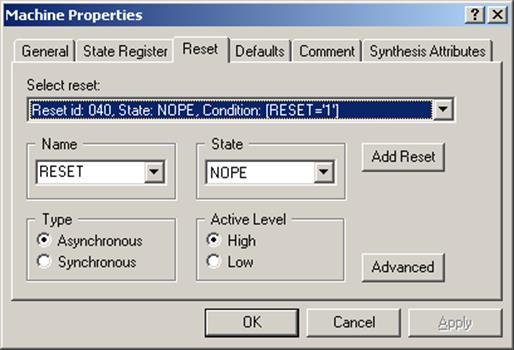
• Define two asynchronous resets on state NOPE
G.15 State Diagram
Now you will define the action for the NOPE state
•
Press the State Action  icon on the
toolbar
icon on the
toolbar
• Click on the NOPE state
• Define Action: red <= ‘0’;
yellow <= ‘0’;
green <= ‘0’;
G.16 State Diagram
Now you will set LIGHT state as hierarchical
• Right click on the LIGHT state
• Select the Properties option
• Check the Hierarchical check-box
• Press the OK button
G.17 State Diagram
Now you will define the contents of hierarchical state
LIGHT
• Select LIGHT state
•
Press the Push Hierarchy ![]() icon on the
toolbar.
icon on the
toolbar.
Window with the new state diagram sheet will appear
G.18 State Diagram
•
To pop up hierarchy level you can use
 icon
icon
•
The ![]() symbol defines entry point
symbol defines entry point
•
The  symbol defines exit point
You can define multiple entry points and more than one exit point as well.
G.19 State Diagram
• Draw this state diagram for the LIGHT sub-state :
• You can resize states if the name doesn’t fit
G.19a State Diagram
You can change some part of state diagram into hierarchical state:
• select part of the diagram
•
Click “Converts to hierarchical state” ![]()
G.20 State Diagram
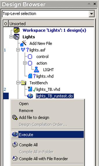
When the diagram is finished,
you can run simulation.
• Run lights_TB_runtest.do macro
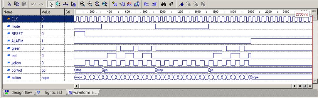
G.21 State Diagram
You should receive results like this:
Appendix H
Junction & Auto Priority
H.1
State Diagram
Junction & Auto Priority
• Create State Diagram
• Add the generated file to the design
• Choose VHDL as a generated language for the State Diagram
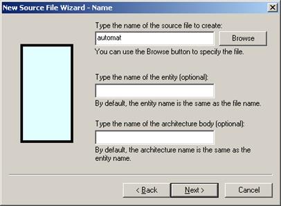
• Type the name of the source file to create
H.2
State Diagram
Junction & Auto Priority
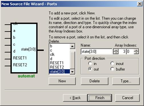
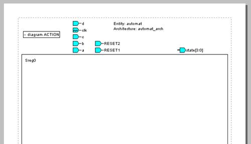
• Add new ports to the State Diagram:
– a: in STD_LOGIC;
– b: in STD_LOGIC;
– c: in STD_LOGIC;
– clk: in STD_LOGIC; // as a clock
– d: in STD_LOGIC;
– RESET1: in STD_LOGIC;
– RESET2: in STD_LOGIC;
– state: out STD_LOGIC_VECTOR (3 downto 0)
• Add new ports to the State Diagram:
– a: in STD_LOGIC;
– b: in STD_LOGIC;
– c: in STD_LOGIC;
– clk: in STD_LOGIC; // as a clock
– d: in STD_LOGIC;
– RESET1: in STD_LOGIC;
– RESET2: in STD_LOGIC;
– state: out STD_LOGIC_VECTOR (3 downto 0)
H.3
State Diagram
Junction & Auto Priority
• Place 7 states on diagram
• Now, we are going to define transitions similar to the ones presented on the picture below, but not in this way…

•
We are going to use “Junction”
H.4
State Diagram
Junction & Auto Priority
• Place “Junction” on the diagram
• Place following “Transitions” between states
• Place “Junction” on the diagram
• Place following “Transitions” between states
H.5
State Diagram
Junction & Auto Priority
• Add two synchronous Resets to State Diagram - use “Add Reset” button in “Machine Properties”
Уважаемый посетитель!
Чтобы распечатать файл, скачайте его (в формате Word).
Ссылка на скачивание - внизу страницы.