• Now, right click on the ENABLE in if statement (line 51) and select Follow Object option. You will see list of processes associated with ENABLE port
• 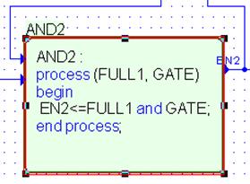
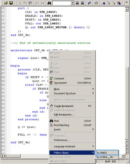 Select /AND2. This will take you to Block Diagram with
highlighted AND2 process
Select /AND2. This will take you to Block Diagram with
highlighted AND2 process
 |
4.14 Dataflow View
• Select EN2 wire, and invoke context menu using right mouse button. Select View in Data Flow option to invoke Data Flow View
4.15 Dataflow View
• Signal View shows a signal or net in the center of the window. Processes on the left side update the signal/net. Processes on the right side read the signal/net.
• Click U2/line__46(may differ depending on your source code) link to see the process driven by EN2
• Process View shows a process in the center of the window represented as a rectangular box with signals/nets read by the process on the left side and signals/nets updated by the process on the right.
• <<>> Displays mappings for respective signals
 |
4.16 Advanced Dataflow View
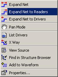
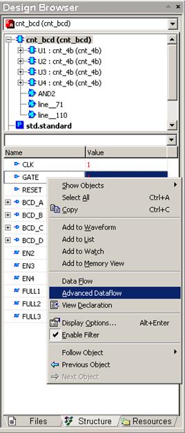
• In the Structure of the design, select GATE input of the CNT_BCD entity and call context menu
• Choose Advanced Dataflow. A terminal symbol will appear in new window
• Invoke context menu for this input terminal terminal and choose Expand Net to Readers
4.17 Advanced Dataflow View
• The Advanced Dataflow window will display all processes, signals connections between them and hierarchy boundaries (port map symbols)
• Current values of the signals are displayed in probes
• Signals read by the process are shown on the left hand side of the symbol
• Signals present on a sensitivity list of a
process are marked with ![]() sign
sign
• Signals “written” by a process are shown on the right hand side of the symbol
• Using the Advanced Dataflow and Expand Net to Readers check how the “ENABLE network” works
4.18 Advanced Dataflow View
• The Advanced Dataflow has two modes of operation: Flat and Hierarchical
• The Hierarchical mode displays instances along with information on their structure
• Turn on the Hierarchical mode using Advanced Dataflow menu Hierarchical Mode option and analyze the “RESET network”
• The Advanced Dataflow has two modes of operation: Flat and Hierarchical
• The Hierarchical mode displays instances along with information on their structure
• Turn on the Hierarchical mode using Advanced Dataflow menu Hierarchical Mode option and analyze the “RESET network”
5.1 Using the Testbench Wizard
• This section will show the following operations:
– How to use the Testbench Wizard
– How to create Single process test bench types
– How to automatically verify the tested unit
5.2 Using the Testbench Wizard
• Using testbenches, you can automatically verify your design.
• In this chapter, you will generate a Single Process testbench.
• The complete testbench file and some additional files will be generated automatically by the Active-HDL Testbench Wizard.
• All stimulus driving inputs of the tested design will be taken from the previously saved waveform file. This way the stimulators and waveform signals will be converted to VHDL.
5.3 Testbench Concept
• The figure below illustrates the concept of
a testbench
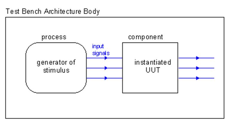
The process implemented in the architecture body of a testbench forces desired
stimulus on the inputs of the tested design unit (Unit Under Test = UUT).
5.4 Using the Testbench Wizard
• Go to the Files tab of Design Browser
Уважаемый посетитель!
Чтобы распечатать файл, скачайте его (в формате Word).
Ссылка на скачивание - внизу страницы.