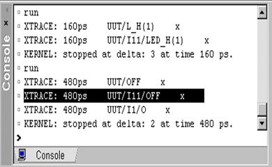
# XTRACE: 160ps UUT/I1/O x
Double click on this line will add the signal with X value to the Advanced Dataflow view where you can explore the design connectivity to find the source of the unknown value.
4.32 Xtrace and Advanced Dataflow
In the figure on the left the it is clearly visible that the cause of an X on the output O of the AND2 module is the X value on BUST signal connected to I0 input. To list all the driving processes in the console window you can use the List Drivers option from the context menu.
4.33 Xtrace and Source Code Crossprobing
The XTrace also supports the message crossprobing to the HDL source of the unknown values. To enable it, use following command after simulation initialization:
xtrace -source -rec *
During the simulation messages in the Console window will be sensitive to double click, and will take you to the source code which caused the unknown value on the signal.

4.34 Signal Agent
The Signal Agent allows monitoring and driving VHDL signals that do not have to be routed via the interface or declared in global packages, which is particularly useful in testbench development and design verification. To use the signal_agent procedure, insert the following library and use clauses:
library aldec;
use aldec.signal_agent_pkg.all;
The Signal Agent joins a source signal with a destination signal. The source drives the destinations as if the signals were connected directly in a simulated model. The signal_agent procedure (stored in the signal_agent_pkg package in the pre-installed aldec library) needs to be called only once. All changes on the source signal will then be transferred to the destination signal.
4.35 Signal Agent
In the signalagent sample design uses the signal_agent procedure to monitor the 4 signals buried deep in the design hierarchy. The /uut/u2/full signal drives the full2 signal located at the top-level region of the design.
Monitoring the /uut/u2/full signal without the signal_agent task requires routing the signal through the interface of each block or defining it in a global package.
architecture beh of testbench is
signal full1, full2, full3 : STD_LOGIC;
begin
signal_agent ( "/uut/u2/full", "full2", 1 );
…
stimulus: process is
begin
-- ...
-- ...
end process stimulus;
end architecture beh;
Design Verification
Running Simulation
Course 5
5. Simulation
Simulation steps:
• Compile the design
• Set the top-level architecture
• Open Waveform Editor
• Drag the signals
• Initialize simulation
• Apply stimulators
• Advance simulation
• Verify results
• Save simulation run
5.1 Compiling Designs
Before you start simulation, you must compile the design files to reflect the latest changes. Remember that saving the source file is not enough. Simulation is based on the entities compiled into the working library.
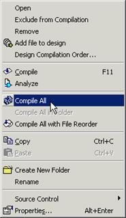 To compile the design you can choose
the Compile All or Compile All in Folder options from the pop up
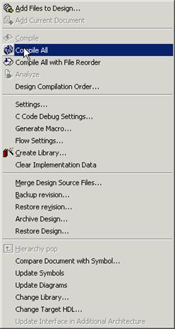
menu in the Design Browser window. Youcan also callthe same commands from
the Design menu.
Note: The Compile All with File Reorder command automatically compiles all design files in the specified compilation order.
5.2 Setting top-level
Simulation is carried out for the selected library architecture called top-level architecture.
• To choose a top-level architecture, expand the working library in the Design Browser window.
• Select the architecture and choose the Set as Top-Level option from the pop-up menu
5.3 Opening Waveform Editor
Simulation results are displayed in the Waveform Editor that is a tool designed to observe simulation results as timing waveforms and to edit simulation test vectors.
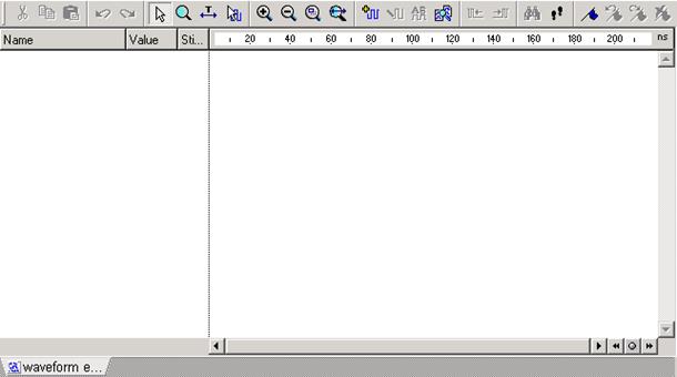
To open the Waveform Editor:
• Click the toolbar button
• Choose New/Waveform
option from the File menu.
5.3 Ref.A Waveform Editor
Уважаемый посетитель!
Чтобы распечатать файл, скачайте его (в формате Word).
Ссылка на скачивание - внизу страницы.