•
• Click on the Apply button and then on the Close button
3.9 Running Simulation
• Prepare a DO macro file with following commands:
run 100 ns
pause
run @200 ns
pause
run @600 ns
pause
run @1200 us
• Save the file as RUN.do and close the editor window
• Switch to Files tab in Design Browser
• Use Execute from context menu for RUN.do macro file
NOTE: 1200 MICRO not NANOSECONDS
3.10 Running Simulation
• Execution of the macro will be interrupted by pause commands. Then you will be able to use the G hotkey to toggle the value of GATE signal
• At 100 ns toggle the GATE signal to 1 and then issue resume command in console to continue the simulation
• At 200 ns toggle the GATE signal to 0 and then issue resume command in console
• At 600 ns toggle the GATE signal to 1 and then issue resume command in console
NOTE: To toggle the GATE signal value, focus has to be set
to Waveform Editor window
3.11 Running Simulation
• Observe when the counter starts counting. /t=650ns/
• You may use the Zoom In ![]() , Zoom Out
, Zoom Out ![]() ,
Zoom To Fit
,
Zoom To Fit ![]() and Zoom Range
and Zoom Range ![]() buttons to change the scale in
the Waveform Viewer
buttons to change the scale in
the Waveform Viewer
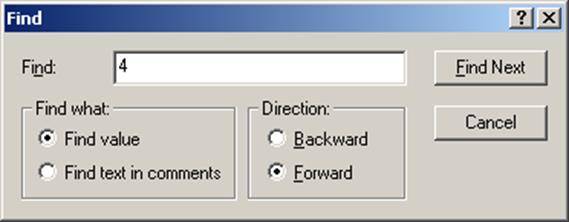
• To quickly find signal values in the Waveform Viewer, right-click on the signal name, select Find. Type the value you want to find, select search direction (forward or backward) and click Find Next.
3.12 Custom Stimulators
• End the simulation (Simulation | End Simulation menu option).
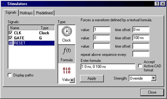
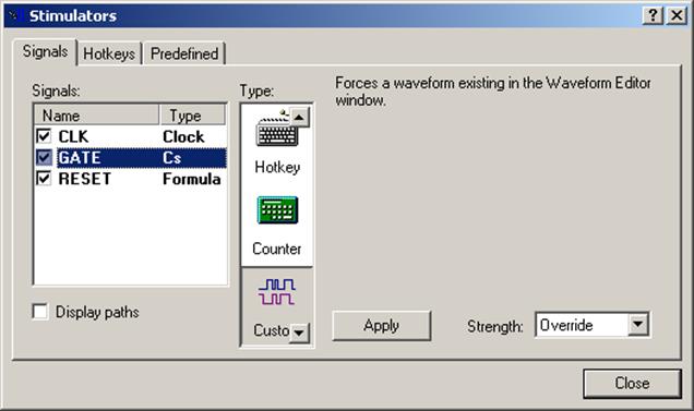
• Replace the Hotkey Stimulator Type for GATE signal with Custom Type. Click on the Apply button and then the Close button
• The Custom Stimulator will use the existing waveform as simulation input
3.13 Bus Display Radix
• You can change display radix and notation of bus signals. To change BCD_A signal display radix, select the bus and invoke the pop-up menu (right click on the signal). Choose the Properties option and the Binary radio-button.
• You can change display radix and notation of bus signals. To change BCD_A signal display radix, select the bus and invoke the pop-up menu (right click on the signal). Choose the Properties option and the Binary radio-button.
3.14 Waveform Display Mode
• You can also modify the size and color of waveform
• For buses you can choose between Literal and Analog display mode
• For scalar signals Literal and Logic modes are available
• Close the waveform and save it as CNT_BCD.AWF
• You can also modify the size and color of waveform
• For buses you can choose between Literal and Analog display mode
• For scalar signals Literal and Logic modes are available
• Close the waveform and save it as CNT_BCD.AWF
3.15 Other Waveform Features
Some additional waveform window features are available during simulation:
– Edit Mode (you can drag signal events to change its shape)
– Measurement Mode (to measure distance between specific points of timing)
– Zoom Mode (zooming of timing)
– Waveform comparison
– Stretch option (you can select waveform signals and stretch their timing)
– Bookmarks operations
– Comments
– Signal sorting
4.1 Debugging features
• This section will demonstrate the following operations:
– How to work with Breakpoints
– How to work with Watch window
– How to Trace the execution of the code
– How to Show Event Source
– How to use Follow Object feature
– How to interpret Dataflow view
– How to use Advanced Dataflow
4.2 Setting up the debug session
Уважаемый посетитель!
Чтобы распечатать файл, скачайте его (в формате Word).
Ссылка на скачивание - внизу страницы.