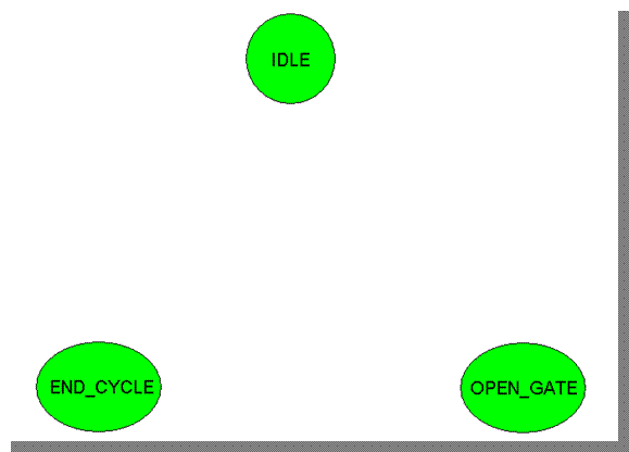
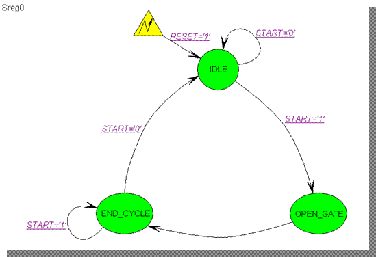
• Please change state names to IDLE, OPEN_GATE and END_CYCLE, as shown in this picture
• If the new name is wider than the state, click inside the state and resize it by dragging the handles
7.5 Creating a State Diagram
You can draw
transitions between states by selecting
FSM | Transition from the menu or the Transition button ![]() in the toolbar and clicking the starting
state, then clicking the target state
in the toolbar and clicking the starting
state, then clicking the target state
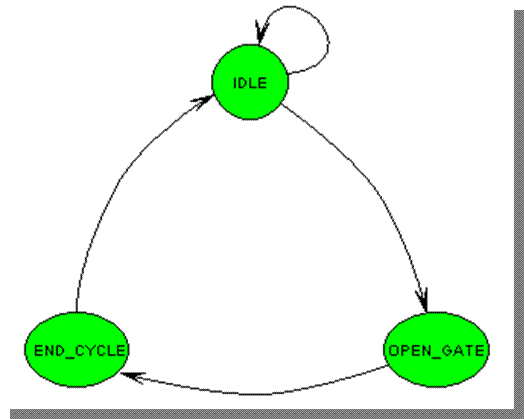
• Please draw transitions as shown in this picture
• To draw a loop transition, click inside the same state twice
• To change the shape of any transition, click on it and drag the handles
7.6 Creating a State Diagram
You can define a
reset state in your FSM by selecting FSM | RESET from the menu or Reset
button ![]() in the toolbar, clicking close to
the reset state to place the reset symbol, then clicking inside the state to
draw the reset transition.
in the toolbar, clicking close to
the reset state to place the reset symbol, then clicking inside the state to
draw the reset transition.
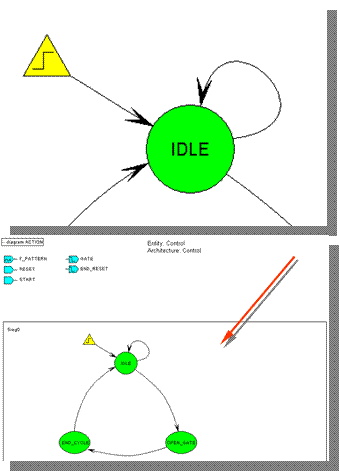
• Please draw the reset symbol and transition as shown in this picture
• To set parameters of the reset signal, you must invoke the Machine Properties window by right-clicking on the rectangular frame surrounding the machine and selecting Properties
 |
7.7 Creating a State Diagram
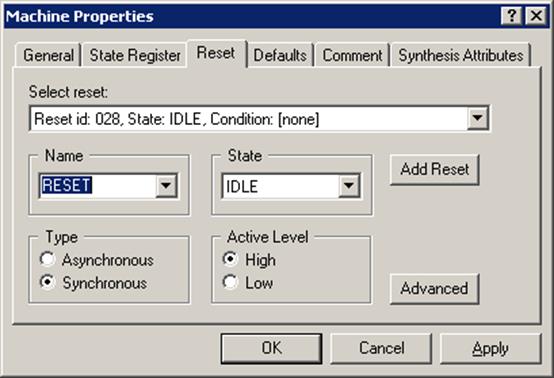
• Click the Reset tab in the Machine
Properties window and select:
- RESET signal in the Name box
- Asynchronous in the Type box
- High in the Active Level box
• Click OK
You can specify
more elaborate
reset conditions by clicking
Advanced and typing an expression describing the reset condition
7.8 Creating a State Diagram
You can add
conditions to the transitions by selecting
FSM | Condition from the menu or Condition button ![]() in the toolbar, clicking the transition and
typing the condition expression
in the toolbar, clicking the transition and
typing the condition expression
• Please add the following conditions:
– START=‘0’ to the loop transition in the IDLE state and to the transition from the END_CYCLE to the IDLE state;
– START=‘1’ to the loop transition in the END_CYCLE state and to the transition from IDLE state to the OPEN_GATE state
7.9 Creating a State Diagram
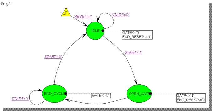
You can add actions to the states by selecting FSM | Action | State from the menu, clicking inside the state and typing the expression(s) that should be executed when in the state.
• Please add the following actions:
GATE<=‘0’;
END_RESET<=‘1’;
to the IDLE state
GATE<=‘1’;
END_RESET<=‘0’;
to the OPEN_GATE state
GATE<=‘0’;
to the END_CYCLE state
The completed diagram is shown in this picture
7.10 Customizing the Generated Code
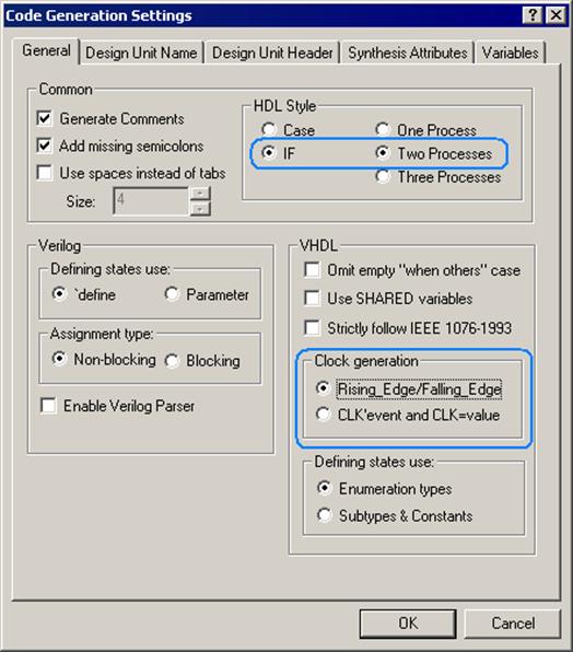
• From FSM menu, choose Code Generation Settings
• Change the HDL Style to use IF statements and use Two Process template
• Use rising_edge / falling_edge functions to detect the clock edges
 |
7.11 Creating a State Diagram
• Save your state diagram (Ctrl+S)
• Right-click on Control.asf in the Design Browser and select Compile; watch as the VHDL code is generated from the state diagram and then compiled (console window)
• Compile the top level block diagram (top_frqm.bde)
• Select top_frqm(top_frqm) entity/architecture pair as your top level
Your design is ready for final testing.
• Save your state diagram (Ctrl+S)
• Right-click on Control.asf in the Design Browser and select Compile; watch as the VHDL code is generated from the state diagram and then compiled (console window)
Уважаемый посетитель!
Чтобы распечатать файл, скачайте его (в формате Word).
Ссылка на скачивание - внизу страницы.