Design Entry & Management
Creating HDL Graphical Modules
Course 2
2. Top-Down Design Concepts
• Start by creating a top level diagram
• Push into individual symbols
• Select your preferred design entry tool:
• BDE – Block Diagram Editor
• HDE – HDL Editor
• FSM – Finite State Machine Editor
• Create the source code
• Compile the entire design sources
2.1 Creating at Top Level Block Diagram
In this section we will implement the top level Block Diagram file to familiarize you with the basic concepts of the Block Diagram Editor. We will also create a State Machine module Control using top-down design methodology.
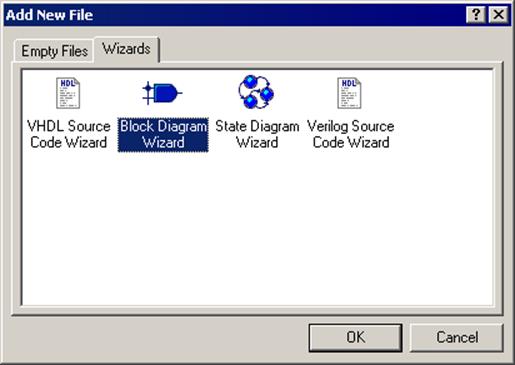
• To create the new block diagram, double click on Add New File from the Files tab on the Design Browser
• Select Wizards tab and double click Block Diagram Wizard
Note that you can also create an empty skeleton file by selecting Empty Files tab in the Add New File window.
• Click Next >
• Type Top_Counter in the first box in the New Source File Wizard - Name window and click Next >
See ref. A for more details
Ref. A The Design Wizards
Design Wizards simplify the creation
process guiding you through the initial stages of design development.
Using design wizards, you will create skeleton files with little effort.
2.2 Creating the Top Level Block Diagram
•
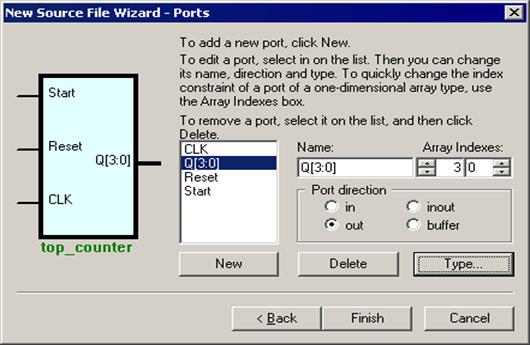
Define the following ports of the top_counter
block diagram:
Input Ports:
- START
- RESET
- CLK
Output Ports:
- Q [3:0]
• Click Finish
Block Diagram Editor (BDE) screen with an empty diagram will appear.
See ref. B for more details
Ref. B Design Wizard - Ports
• To add a port, click the New button and type the name of the port.
• To change a port type, click the radio buttons in the Port direction box. There are four types:
– In
– Out
– Inout
– Buffer
• To remove any port, click its name on the list and click the Delete button.
• To create a bus, add a new port name and click the Array indexes arrows to specify the bus width.
2.3 Creating the Top Level Block Diagram
•
Click the Fub button on the BDE
toolbar and create fub to the right of the START, RESET and CLK and input port
symbols by clicking in the one corner of the fub and dragging to the opposite
corner.
The fub you are drawing
should look like this:
NOTE: FUB is a symbol ‘in the process of creation’ and can be converted to a regular symbol when completed. The main difference between a fub and a symbol is that you can have multiple instances of the same symbol, but only one fub.
2.4 Creating the Top Level Block Diagram
• Click the Wire button on the BDE toolbar and drag three horizontal wires from the START, RESET and CLK input port symbols to the U0 fub;
*
please note that three input
pins are automatically created
in the fub
•
Hit Esc key to return to
Select mode
•
Double-click “Fub0” label below
the fub and change fub name
to CONTROL
•
Right click in the fub body
and select Edit to switch
to Edit mode
2.5 Creating the Top Level Block Diagram
•
Drag Out pin from the Add New Pin
window to the fub and drop it on the right-hand edge to create Pin1;
repeat
dragging to create Pin2
• Double-click Pin1 and change its name to Clock
• Double-click Pin2 and change its name to RST
• Click outside the fub and answer Yes when asked if you want to save changes to the fub
2.6 Creating the Top Level Block Diagram
•
The completed fub should look
like this:
(we will fill the fub contents
after completing our top level
block diagram)
•
We can now proceed to placing the
remaining symbol on the
top_counter block diagram.
To place the symbol from the library,
we will use the Symbol Toolbox window.
To open it, use the Show Symbol Toolbox button.
2.7 Creating the Top Level Block Diagram
Уважаемый посетитель!
Чтобы распечатать файл, скачайте его (в формате Word).
Ссылка на скачивание - внизу страницы.