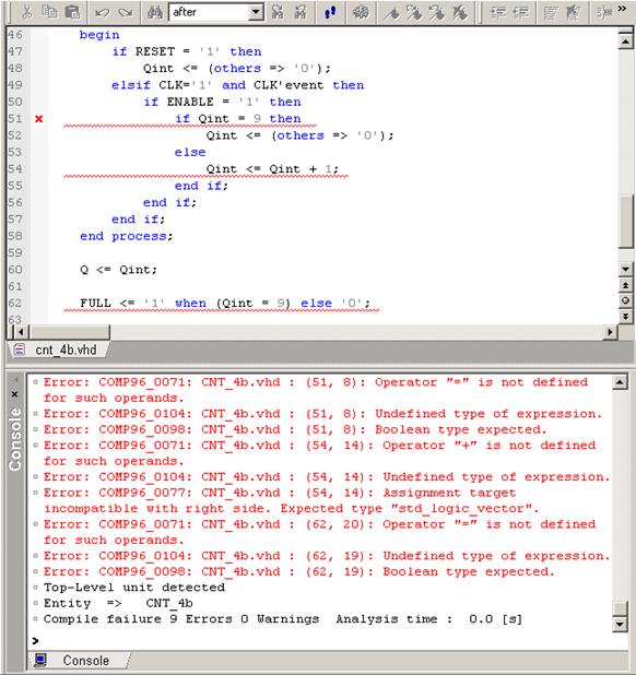
• Errors will occur. Console window will show the error messages and erroneous lines will be highlighted in the HDL editor
• Double-click on an error info in the Console to jump to the incorrect code
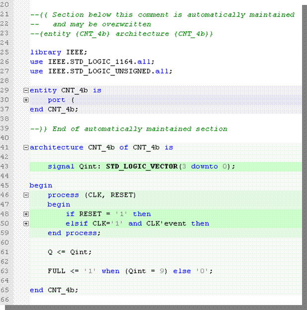
2.9 Creating the CNT_4b module
• Add the use clause for the IEEE std_logic_unsigned package (before the entity declaration)
• From the Edit menu, choose the Document Structure | Generate Structure to enhance legibility of the code
• The complete source code should look like shown in the picture
2.10 Simulating the CNT_4b module
• Save the CNT_4b.vhd file
• Compile the CNT_4b.vhd file (select the CNT_4b.vhd item in the Design Browser and use the Compile option from the context menu)
2.11 Simulating the CNT_4B module
• Initialize simulation (Simulation | Initialize Simulation option)
• Invoke the new Waveform Editor window - click on the icon
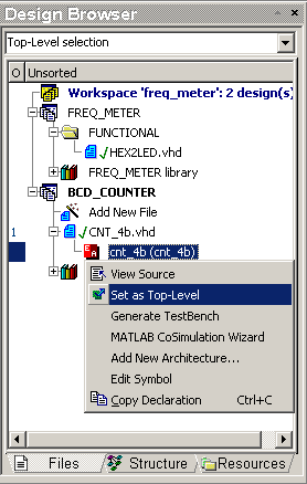
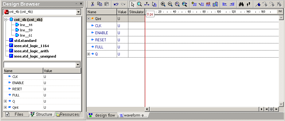
• Click on the cnt_4b(cnt4b) and drag & drop signals into the Waveform Editor window. To view the simulation top-level hierarchy, click the structure tab at the bottom of the Design Browser.
2.12 Simulating the CNT_4B module
• The force command used from the
console or in macro files lets you create any waveform using the following
syntax:
force signal_namevalue1 time1, value2
time2 -r period
•
where more than two pairs of signal value and time can be specified and -r switch is skipped for aperiodic waveforms
• Select File | New | Macro from the menu
• Type the following lines into the document:
force signal_namevalue1 time1, value2
time2 -r period
•
2.13 Adding the DO macro to the project
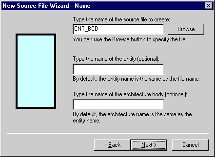
• Select File | Save as from the menu, type CNT_4b in the File name box and select the Automatically add new files to design checkbox.

2.14 Simulating the CNT_4B module
• Switch to Files view in the Design Browser: special icon for the saved macro should be visible.
• Close the cnt_4b.do file; the
Waveform should be visible again
in the Document window
• Right click cnt_4b.do icon in the
Design Browser and select Execute from the context menu.
Formula text should appear in the Stimulator column for the CLK,
ENABLE and RESET signals
• Right click cnt_4b.do icon in the
Design Browser and select Execute from the context menu.
Formula text should appear in the Stimulator column for the CLK,
ENABLE and RESET signals
2.15 CNT_4B module description
• Adjust the simulation step to 100 ns if
necessary ![]()
• Click the ![]() icon
to progress the simulation
icon
to progress the simulation
• After clicking two more times on the ![]() icon, the waveforms should look like this:
icon, the waveforms should look like this:
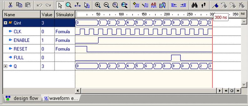
• End simulation (Simulation | End Simulation option)
• Save the waveform into the file as CNT_4b.awf
• Close all documents
2.16 Creating the CNT_BCD module
• To complete the 4-decades counter, create a new Block Diagram
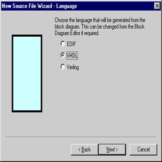
• Use the New Source File Wizard (File
| New | Block Diagram from the menu) to create CNT_BCD component.
Remember to select VHDL as the target language.
2.17 Creating CNT_BCD module-ports
• Add the input ports of the STD_LOGIC type:
– CLK
– GATE
– RESET
• Add the output ports of the STD_LOGIC_VECTOR:
– BCD_A[3:0]
– BCD_B[3:0]
– BCD_C[3:0]
– BCD_D[3:0]
• Click Finish
• Add the input ports of the STD_LOGIC type:
– CLK
– GATE
– RESET
• Add the output ports of the STD_LOGIC_VECTOR:
– BCD_A[3:0]
– BCD_B[3:0]
– BCD_C[3:0]
– BCD_D[3:0]
• Click Finish
Уважаемый посетитель!
Чтобы распечатать файл, скачайте его (в формате Word).
Ссылка на скачивание - внизу страницы.