If Batch mode is chosen, then the synthesis process will start automatically.
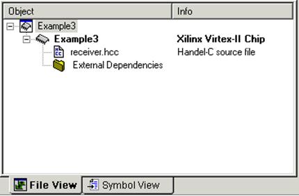
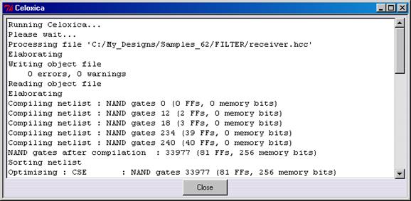
14.6 C synthesis
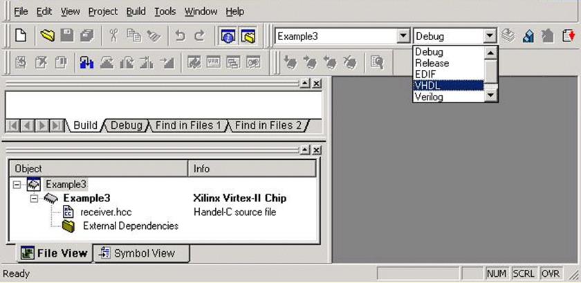
Before you start building, you should select the VHDL configuration.
In order to select it, choose Set Active Configuration from
the Build menu or use the pull-down menu as it is shown in the figure below
14.7 C synthesis
After the active configuration has been set, you can build the project by using the Build (F7) command from the Build menu.
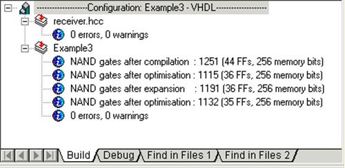
When the project is built, you can find on the Build tab information on an
estimated usage of resources.
14.8 Adding file to Active-HDL design
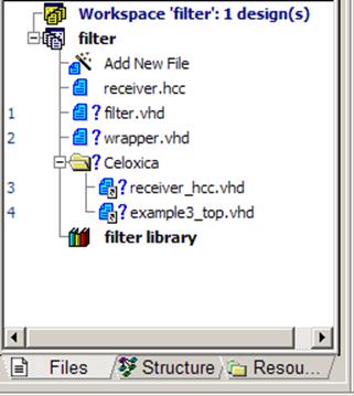
Close DK Design Suite and switch to Active-HDL. After the project has been built, the Celoxica subfolder is created in the design folder. In this folder, the files generated by DK
Design Suite will be stored. The Refresh File List button in the Design Flow window allows you to point to the files that should be added to the filter design.
Press the browsing button (...) in the Choose Source File dialog box and then select the required files from $DSN/Celoxica/Vhdl.
The design tree containing all files is presented below.
14.9 Synthesizing the Design
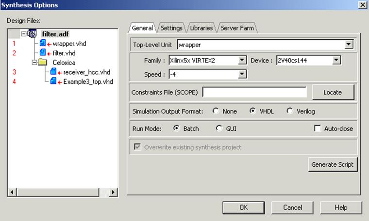
Open the Synthesis Options window from Flow.
In this window, specify the name of the top-level unit (wrapper) and other options on the General tab as it is shown below
14.10 Synthesizing the Design
- Additional libraries
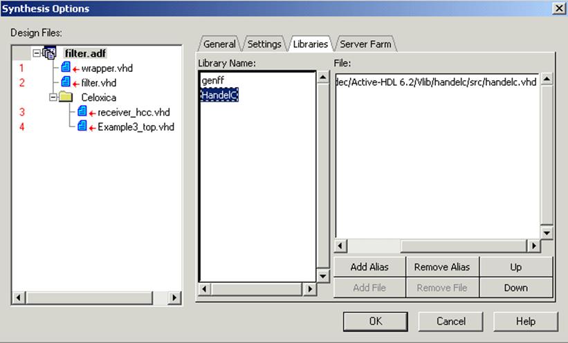
Open the Libraries tab and specify a library (alias) used by the synthesis tool.
Click Add Alias, type in HandelC and press OK.
In the Add File window, browse to the $ALDEC/Vlib/handelc/src subfolder and select the handelc.vhd file.
Next, press the Open button.
14.11 Synthesizing the Design
Close the Synthesis Options window by clicking OK.
When you specify all settings you can run the synthesis by pressing the Synthesis button in the Design Flow window.
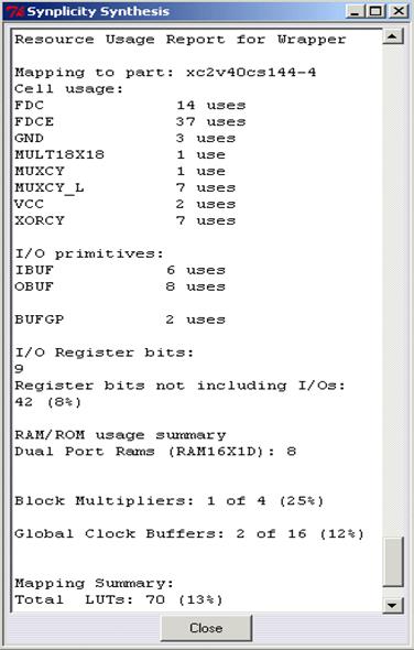
After the synthesis has finished, you can view the synthesis report in the window shown below or by opening the log file.
14.12 Post-synthesis Files
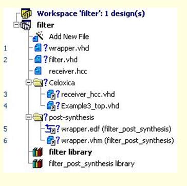
The post-synthesis subfolder is added to the design tree.
It contains two files: wrapper.edf used by the implementation tool and wrapper.vhm that can be used to run post-synthesis simulation.
Now, we can proceed to start an implementation process
14.13 Implementing the Design
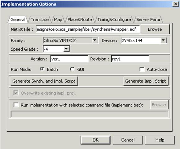
You can run the implementation with the default settings or modify them in the Implementation Options window. In this window, after you specify all settings you can run the implementation by pressing the Implementation button in the Design Flow window .
14.14 Implementation results
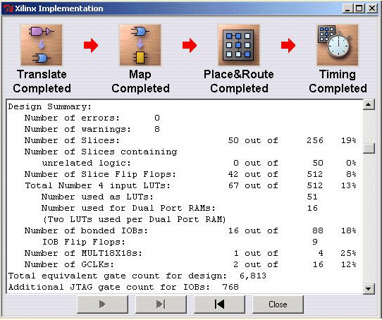
You can review the implementation report in the window shown below or open the log file in the HDL Editor window.
14.15 Design after implementation
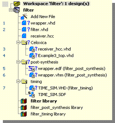
After the implementation has completed, you can compile time_sim.vhd and run the timing simulation of the filter design, which allows you to check the implementation results.
Active-HDL
HDL Design & Verification
LAB
Outline
1. Creating a Behavioral Design
2. Creating CNT_BCD module
3. Simulating with the waveforms
4. Debugging Features
5. Using Testbench Wizard
6. Creating top level Block Diagram
7. Creating State Diagrams
8. Simulating Top Level
Appendices
A. Synthesis & Implementation
B. Using Code Coverage
C. Importing Foundation Designs
D. Using Verilog PLI
E. WAVES Testbenches
F. How to create a Diagram from HDL
G. State Diagram
H. State Diagram - Junction & Auto Priority
I. VHPI Interface
1.1 Creating a Behavioral Design
• The training is based on a simple frequency meter design with a BCD counter and a 7-segment LED display.
Уважаемый посетитель!
Чтобы распечатать файл, скачайте его (в формате Word).
Ссылка на скачивание - внизу страницы.