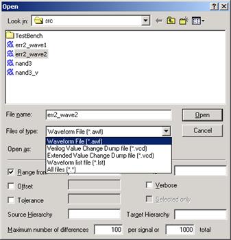
• A number of differences detected during the comparison can be precisely specified. If it is exceeded, the comparison will be stopped immediately.
5.36 Using Macro Commands for Simulation
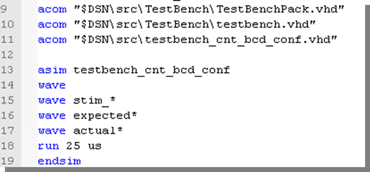
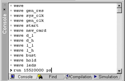
Active-HDL provides a macro command language for manual entering of such simulation commands as forcing signal values, assigning formulas and executing simulation steps. You can force a value on a signal at any time during simulation by entering the appropriate macro command in the Console window. You can also use macro commands to add forced signals to the Waveform Editor, etc.
5.37 Timing Simulation
Timing Simulation steps:
• Import structural files
• Import timing constraints - SDF
• Set the top-level architecture
• Open Waveform Editor
• Add the signals
• Initialize and run simulation
• Apply stimulators
• Measure time differences
• Save simulation run
5.38 VITAL and SDF
Active-HDL simulator can perform timing simulation based on HDL structural netlists, EDIF netlists, and SDF files. These files are created during the synthesis and Place & Route processes. The simulator provides built-in acceleration for VITAL packages ver. 3.0.
HDL and EDIF netlists contain structural connections between components and SDF (Standard Delay Format) files contain specific timing constraints of a programmable device.
To simulate such netlists in Active-HDL, you need to add these files to the current design. You can do it by using the Add New File wizard. For details, refer to the previous courses.
5.39 Generics
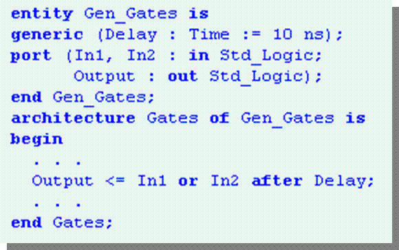
You can perform
timing simulation at any stage of design development. This, however, requires
some effort on your side. VHDL language supports generics that are timing
parameters describing delays in a design. If you created
assignments in the model
description using generics,
you can assign certain
values to them externally
and, therefore, simulate
real programmable device
delays.
5.40 Timing Settings
You can set the timing simulation settings in the Design Settings window. Here you can specify if the simulator should ignore VITAL glitches for VHDL and specify the type of delays for Verilog. You can also load the SDF file(s) for a specific region to enable timing simulation (not required for Verilog).
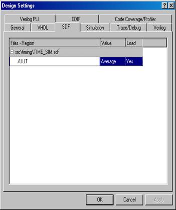
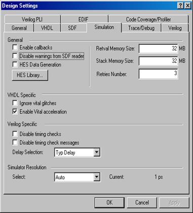
5.41 Timing Settings
You can set the simulation settings from the macro command file. For this purpose use the asim macro command. An example usage is shown below:
asim freq_top -sdftyp /UUT/U1=$DSN\src\TIME_SIM.SDF
freq_top
- Specifies the name of the top-level configuration to be simulated.
-sdftyp
- Annotates VITAL cells in the specified region with typical timing values from the SDF file.
/UUT/U1=$DSN\src\TIME_SIM.SDF
- Specifies the design region into which timing data from the specified SDF file are to be loaded.
5.42 Running Timing Simulation
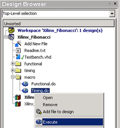
• Open the Xilinx_Fibonacci design.
• Expand the Macro folder
• Execute the Timing.do file
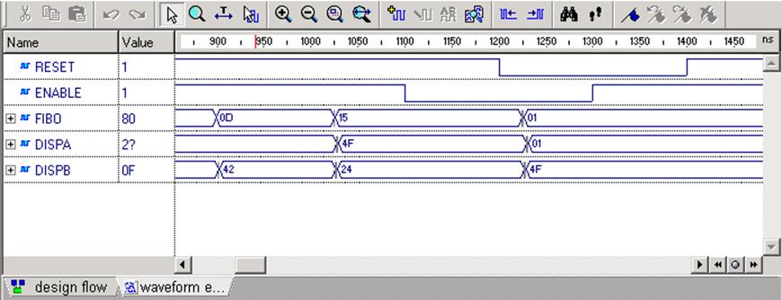
• Observe the simulation run
5.43 Measuring Distance between Events
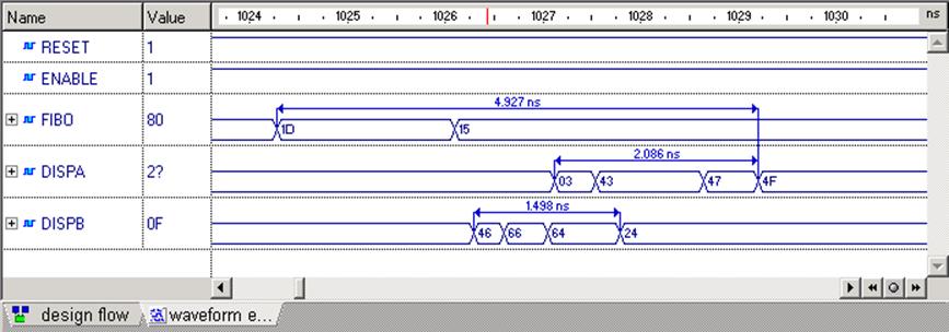
During the timing simulation, the most important issue is to check the timing constraints. Active-HDL facilitates this process providing you with Measurement mode in the Waveform Editor window.
5.44 Measuring Distance between Events
• Switch to the Measurement mode
clicking ![]() button.
button.
• Click the event at which you want to anchor one end of the measured area and hold the mouse button.
• Drag the mouse pointer to stretch the measured area (displayed on grayed background) to another event. The time distance is displayed in the tooltip.
• Release the mouse button.
Note: You can set
the Snap to event
option in the Preferences/
Waveform window to
automatically snap the
cursor while measuring events.
Уважаемый посетитель!
Чтобы распечатать файл, скачайте его (в формате Word).
Ссылка на скачивание - внизу страницы.