 , (4.38)
where R – operating load, D – cylindrical rigidity, а – distance from the plates center to a point of load attack, b – plates radius, r – current radius of considered section.
 . (4.39)
Flexure of the bottom under action of the distributed load:
 . (4.40)
For the considered bottom a=0,86 m, b=1,86 m, R=3000 N, р=105 P. After corresponding substitutions the formula (4.38) will take the form:
 (4.41)
For definition
of stress we shall find the second derivative of a flexure on coordinate r ![]() :
:
 . (4.42)
Stresses in the bottom we shall determine under the formula:
 , (4.43)
where E=2.2·105 MP – Jung's module, μ=0.3 – Poisson factor.
Cylindrical rigidity is defined under the formula:
 . (4.44)
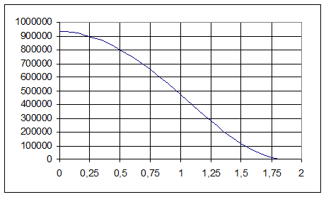
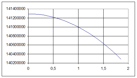
Having substituted the received values in the formulas (4.41) and (4.43) we shall receive function of flexures change and stresses in the bottom on distance from an axial line up to considered section. Calculations are lead by means of program Excel, the received results are presented in table 4.6. Graph are presented in figures 4.8 and 4.9.
Table 4.6. Flexure of the bottom and stress in it dependence from radius of considered section
|
r, m |
0 |
0,2 |
0,4 |
0,6 |
0,8 |
1 |
1,2 |
1,4 |
1,6 |
1,86 |
|
|
0,93 |
0,91 |
0,85 |
0,75 |
0,62 |
0,47 |
0,32 |
0,17 |
0,06 |
0 |
|
|
141,3 |
141,28 |
141,25 |
141,19 |
141,1 |
141 |
140,87 |
140,7 |
140,54 |
140,28 |

Figure 4.8. The graph of flexure dependence from radius of considered section.

Figure 4.9. The graph of stress dependence from radius of considered section..
It is obvious, that the maximal value of stress in the center of the chamber bottom and makes 141,3 MP.
The load factor can be defined under the formula:
 , (4.45)
where ![]() – long-term strength,
– long-term strength, ![]() = 210 MP; smax – the maximal calculated
stress arising in the bottom of the vacuum chamber at its deformation, smax = 141,3 MP.
= 210 MP; smax – the maximal calculated
stress arising in the bottom of the vacuum chamber at its deformation, smax = 141,3 MP.
As a result of calculation under the formula (4.45) we receive:

The design of the bottom is chosen correctly and will take operating loads as satisfies to strength condition (4.45).
The design procedure of the given section of work is taken from [26].
Physical reliability of the vacuum chamber bottom can be defined under the formula:
|
|
where σmax – true value of the maximal calculated stress in the bottom, σmax141,3 MP;
s(σ) – the dispersion of the given stress;
s(σmax) – the dispersion of true stress value.
The given stress ![]() MP, the given stress dispersion
MP, the given stress dispersion ![]() MP.
MP.
The true stress value in the vacuum chamber bottom is defined under the formula:
|
|
The dispersion of true stress value in the vacuum chamber bottom can be determined under the formula:
|
|
where σ(r) - radial dispersion of considered section, σ(r)=0,45 m.
Partial derivative of the stress in the bottom on considered section radius is possible to define under the formula:
|
|
 MP.
MP.
Substituting the received value in the formula (4.12), we shall receive:
![]() .
.
As a result of corresponding substitution in the formula (4.10), we receive:
 .
.
Уважаемый посетитель!
Чтобы распечатать файл, скачайте его (в формате Word).
Ссылка на скачивание - внизу страницы.