- The vacuum chamber (3 compartments);
- Evacuation system of residual atmosphere from the chamber;
- AAL - the accelerator with an anode layer for products surface clearing;
- MAS - for drawing a covering;
- Repository and feed of working substance system;
- Power-supply system;
- Control and inspection system of installation.
Technological process occurs as follows:
- Products are installed on a special tray (15 pieces) and loaded into a loading compartment;
- The chamber is pressurized;
- The residual atmosphere from the chamber is pumped out;
- There is a process of details surface preparation to the covering deposition, namely cleaning of a details surface;
- Covering deposition on a detail;
- Floodgates are closed and occurs letting-to-atmospheric air in loading and unloading compartments, thus in a technological compartment the vacuum is kept;
- We make loading of the following batch workpieces and unloading of already processed.
The design of evacuation system provides such evacuation modes, as forevacuum evacuation by mechanical pumps and high-vacuum evacuation by turbo-molecular pump of each compartment.
Such system allows accelerating evacuation process because during loading-unloading of products in a technological compartment working pressure is kept and evacuation is made only of loading and unloading compartments.
The design of technological compartment is presented on sheet ХАИ.461.06.ДП.12.ВО.03.
For uniform covering deposition and processing of products from different directions it are used six magnetron atomizing systems located on both side of every row of products. Each detail rotates about the axis, moving thus along the chamber. It allows providing more uniform covering deposition on a products surface.
Let's consider design of MAS. In the given work the planar magnetron system of the rectangular form is designed. At designing elements of MAS it is necessary to provide performance of following requirements:
- An opportunity of direct contact of the internal target side with a cooling liquid;
- An opportunity of cooling liquid prorolling;
- Tightness of cathodic unit;
- Constructive completeness of cathodic and anode unit, their simple enough branch from the vacuum chamber (assembly modularity).
The system from six MAS represents the separate module which fastens on a technological compartment of the chamber cover by means of flange. Everyone MAS, in turn, also fastens to a flange. As a whole system MAS represents three set of magnetrons, located against each other in such a manner that during work of installation each of three lines of processable products moves between three magnetrons.
Let's make stress calculation of the vacuum chamber bottom. Calculation is spent, considering the bottom as a casing. The casing is a body, at which one of three measurements is much less than two others.
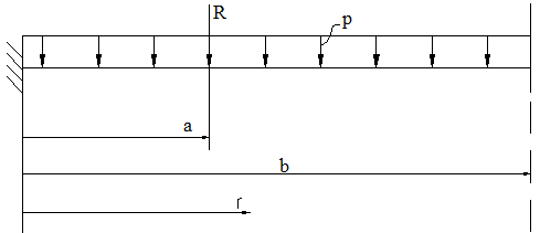
On the bottom of the vacuum chamber act: the distributed load - difference of pressures inside and outside the chamber (р=105 Па); the concentrated load - weight of cathodic units of magnetron atomizing systems and the accelerators with an anode layer (R=3000Н). Acting loadings are shown in figure 4.7.

Figure 4.7. The scheme of loads action on the vacuum chamber bottom
We considered only the bending moment from acting loadings.
For stress definition arising at the bending moment, we shall define a flexure of the bottom from acting loadings.
ω=ω1+ω2, (4.37)
where ω, ω1, ω2, – a total flexure of the bottom and flexures of the bottom from loads R, р accordingly.
The flexure of the plate under action of the concentrated load is defined under the formula:
Уважаемый посетитель!
Чтобы распечатать файл, скачайте его (в формате Word).
Ссылка на скачивание - внизу страницы.