|
№ |
section |
L, sm |
|
|
|
1 |
object input |
- |
0,103 |
0,096 |
|
2 |
pipeline |
30 |
0,096 |
0,089 |
|
3 |
valve |
35,5 |
0,089 |
0,087 |
|
4 |
pipeline |
8 |
0,087 |
0,085 |
|
5 |
boot |
12 |
0,085 |
0,082 |
|
6 |
pipeline |
55 |
0,082 |
0,07 |
|
7 |
valve |
35,5 |
0,07 |
0,067 |
|
8 |
pipeline |
37 |
0,067 |
0,06 |
|
9 |
TMP input |
- |
0,06 |
0,06 |

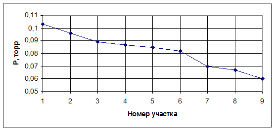
Figure 4.4. The schedule of pressure distribution on the pipeline length of the second section of vacuum system.
Третий участок вакуумной системы представляет собой последовательно соединенные трубопроводы. Режим течения газа на третьем участке вакуумной системы - молекулярно-вязкостный. Расчетные характеристики этого участка определяются аналогично характеристикам второго участка.
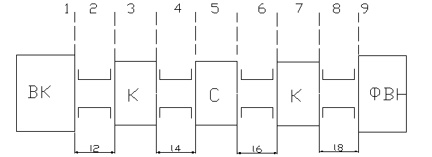
Схема участка изображена на рисунке 4.5.

Рисунок 4.5. Схема третьего участка вакуумной системы
Конструктивно назначаем длины трубопроводов L2=49 sm, L4=14 sm, L6=48 sm, L8=37 sm.
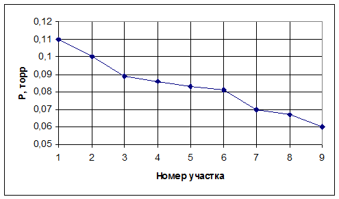
Полученные значения давления заносим в таблицу и строим график распределения давления по длине трубопровода на втором участке вакуумной системы.
Таблица 4.5. Распределение давления по длине трубопровода на третьем участке вакуумной системы
|
№ |
Участок |
L, sm |
|
|
|
1 |
Вход в объект |
- |
0,11 |
0,1 |
|
2 |
Трубопровод |
49 |
0,1 |
0,089 |
|
3 |
Клапан |
35,5 |
0,089 |
0,086 |
|
4 |
Трубопровод |
14 |
0,086 |
0,083 |
|
5 |
Сильфон |
12 |
0,083 |
0,081 |
|
6 |
Трубопровод |
48 |
0,081 |
0,07 |
|
7 |
Клапан |
35,5 |
0,07 |
0,067 |
|
8 |
Трубопровод |
37 |
0,067 |
0,06 |
|
9 |
Вход в ФВН |
- |
0,06 |
0,06 |

Рисунок 4.6. График распределения давления по длине трубопровода на третьем участке вакуумной системы.
We consider, that the gas current is isothermal, i.e. pV=const.
For high-vacuum pump at a molecular mode of gas current on the pipeline when Sн=const, U=const and Q~0, time of the transient mode is defined under the formula:
 , (4.36)
where P1-pressure in the beginning of the section; P2-pressure in the end of a section.
Time of the transient mode for the section from pump DRYVAC 100S up to the vacuum chamber, from atmospheric pressure up to the pressure of high-vacuum pump MAG2000 S/ST start is determined:

On a section from TMP up to the vacuum chamber at achievement of working pressure when three pumps are turned on:

General time of achievement of necessary pressure is 7.1 minutes that meets the requirements; hence pumps are picked up correctly.
The majority of modern spraying machines of magnetron type are equipped by microprocessor devices for management of technological process.
Уважаемый посетитель!
Чтобы распечатать файл, скачайте его (в формате Word).
Ссылка на скачивание - внизу страницы.