We calculate pressure distribution on length of the pipeline. Effective pump speed is expressed by ratio:
 , (4.17)
 l/s.
l/s.
Pressure upon the input of the first section is defined by the equation:
 , (4.18)
where  l/s, as simultaneously works three pump
lines.
 torr.
torr.
Conductivity of the first section is described by expression:
 , (4.19)
 l/s.
l/s.
Effective pump speed is defined by expression (4.17):
 .
.
 l/s.
l/s.
Pressure at the end of the first section is defined under the formula:
 , (4.20)
 torr.
torr.
Pressure at the beginning of the second section is equal to pressure upon
the end of the first section ![]() . Conductivity of the pipeline is equal:
. Conductivity of the pipeline is equal:
 , (4.21)
 l/s
l/s
Effective pump speed is defined by expression (4.17):
 .
.
 l/s.
l/s.
Pressure at the end of the second section is defined by expression (4.20):
 ,
,
 torr.
torr.
Pressure at the beginning of the third section is equal to pressure upon
the end of the second section ![]() . Conductivity of the pipeline is equal:
. Conductivity of the pipeline is equal:
 , (4.22)
 l/s.
l/s.
Effective pump speed is defined by expression (4.17):
 .
.
 l/s.
l/s.
Pressure at the end of the third section is defined by expression (4.20):
 ,
,
 torr.
torr.
Pressure at the beginning of the fourth section:
![]() . Conductivity of the pipeline is equal
to infinity. Pressure at the end of the fourth section is defined by expression
(4.20):
. Conductivity of the pipeline is equal
to infinity. Pressure at the end of the fourth section is defined by expression
(4.20):
 ,
,
 torr.
torr.
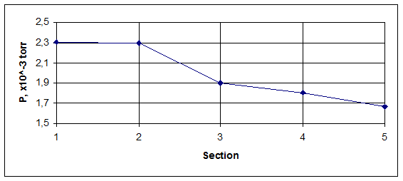
The received results of pressure we bring in the table and build the schedule of pressure distribution on the pipeline length of the first section.
Table 4.3. Pressure distribution on the pipeline length of the first section of vacuum system
|
N |
section |
L, m |
|
|
|
1 |
object input |
- |
|
|
|
2 |
pipeline |
58 |
|
|
|
3 |
valve |
80 |
|
|
|
4 |
pipeline |
21 |
|
|
|
5 |
TMP input |
- |
|
|

Figure 4.2. Pressure distribution on the pipeline length of the first section of vacuum system.
The second section of vacuum system represents consistently connected pipelines.
The scheme of a section is represented in figure 4.4.

Figure 4.3. The scheme of the second section of vacuum system
The general conductivity
of the section of vacuum system from forepump DRYVAC 100S with conductivity  [23] up to TMP:
 , (4.23)
 l/s.
l/s.
We define preliminary ratio between conductivities of separate sections: U21=U22=U24=U25=U26=U28=U, U23=U27=Uк=550 l/s. We determine the general conductivity of all section from expression:
 , (4.24)

 l/s.
l/s.
Constructively we appoint lengths of pipelines L2=30 sm, L4=8 sm, L6=55 sm, L8=37 sm.
We define a gas flow mode on the
pipeline by working pressure of the vacuum pump ![]() torr and by
diameter of an entrance branch pipe of the pump dвх=6.3 sm.
torr and by
diameter of an entrance branch pipe of the pump dвх=6.3 sm.
The free length of gas molecules (expressed in sm.) depending on pressure is defined by expression (4.10):
|
|
 sm.
sm.
We define Knudsen criterion under the formula (4.11):
|
|
 .
.
The received result 1,5> Kn> 0.005, that corresponds to molecular-frictional mode of gas current. In this mode conductivity of the pipeline is defined under the formula:
|
|
(4.25) |
Уважаемый посетитель!
Чтобы распечатать файл, скачайте его (в формате Word).
Ссылка на скачивание - внизу страницы.