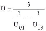
 , (5.7)
 l/s.
l/s.
From pump speed it was chosen 3 turbo-molecular pumps MAG 2000 СT [23].
For maintenance of work of three TMP it is used 3 forepumps DRYVAC100S with pump speed equals S=100 m3/h=27.8 l/s [23].
Table 4.1. Spilling characteristics of the turbo-molecular pump MAG 2000 СT
|
Working range of pressure |
10-9 – 10-3 torr |
|
Pump speed |
2000 l/s |
|
Limiting pressure |
10-9 torr |
|
Diameter of an inlet branch pipe |
250 mm |
|
Diameter of a final branch pipe |
63 mm |
|
Recommended forepump |
DRYVAC100 |
|
Weight |
62 kg |
Table 4.2. Spilling characteristics of the vacuum pump DRYVAC100S
|
Working range of pressure |
|
|
Pump speed |
100 m3/h |
|
Limiting pressure |
10-4 torr |
|
Diameter of an inlet branch pipe |
63 mm |
|
Diameter of a final branch pipe |
40 mm |
|
Length |
866 mm |
|
Width |
450 mm |
|
Height |
720 mm |
|
Weight |
220 kg |
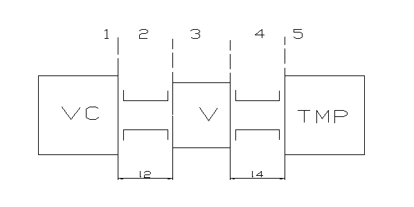
The scheme of the first section of vacuum system is presented in figure (4.1).
In system it is used three turbo-molecular pumps. We shall consider the first section from the vacuum chamber up to one of pumps, having accepted an assumption, that on each pump is necessary one third from total leakage

Figure 4.1. The scheme of the first section of vacuum system
The general conductivity of the section of vacuum system from high-vacuum
pump with
productivity ![]() l/s up to pumped out object is
described by dependence:
l/s up to pumped out object is
described by dependence:
 (4.8)
(4.8)
 l/s.
l/s.
We define preliminary ratio between conductivity of
separate
sections: ![]() ; conductivity of valve DN 250
; conductivity of valve DN 250 ![]() l/s [23], conductivity of the pump
is equal to infinity. For consistently connected elements the general
conductivity is determined by following expression:
l/s [23], conductivity of the pump
is equal to infinity. For consistently connected elements the general
conductivity is determined by following expression:
 , (4.9)
then
 ,
,
 l/s.
l/s.
Constructively
we appoint lengths of pipelines L2=58 sm, L4=
21 sm. We
define a gas flow mode on the pipeline on limiting pressure of the vacuum
chamber ![]() and diameter of an entrance branch
pipe of the pump dвх=25 sm. Free length of gas molecules (expressed in sm.) depending on
pressure:
and diameter of an entrance branch
pipe of the pump dвх=25 sm. Free length of gas molecules (expressed in sm.) depending on
pressure:
 , (4.10)
 sm.
sm.
We define criterion Knudsen - the attitude of free length of gas molecules to the effective size:
 , (4.11)
 .
.
As the received ratio is more, than 1,5, a gas flow mode in the pipeline - molecular.
For a molecular flow mode diameter of the pipeline is determined by following dependence:
 , (4.12)
 sm.
sm.
Constructively is accepted d2=d4=dвх then conductivity at the input in the pump is equal to infinity.
We define conductivity of pipelines with amendment to diameter:
 , (4.13)
 l/s,
l/s,
 l/s.
l/s.
Let's define input conductivity in object (the characteristic sizes а=1,83 m,b=0,83 the m,l=0,86) by dependence:
 , (4.14)
where φ=1,22 at а/b=2,2.
 l/s.
l/s.
The general conductivity of system from pumped out object up to the vacuum pump is determined from expression:
 , (4.15)
 l/s.
l/s.
The use factor of the vacuum pump is equal:
 , (4.16)

![]() - hence, the system is calculated correctly.
- hence, the system is calculated correctly.
Уважаемый посетитель!
Чтобы распечатать файл, скачайте его (в формате Word).
Ссылка на скачивание - внизу страницы.