8 HOST (PCI/USB) PORT
Figure 8-0.
Listing 8-0.
Table 8-0.
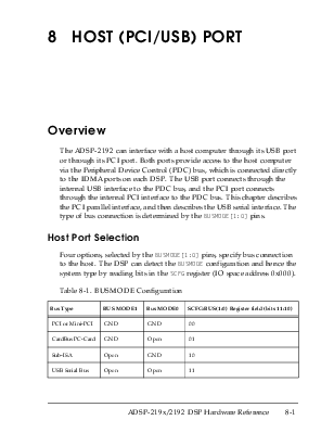
The ADSP-2192 can interface with a host computer through its USB port or through its PCI port. Both ports provide access to the host computer via the Peripheral Device Control (PDC) bus, which is connected directly to the IDMA ports on each DSP. The USB port connects through the internal USB interface to the PDC bus, and the PCI port connects through the internal PCI interface to the PDC bus. This chapter describes the PCI parallel interface, and then describes the USB serial interface. The type of bus connection is determined by the BUSMODE[1:0] pins.
Four options, selected by the BUSMODE[1:0] pins, specify bus connection to the host. The DSP can detect the BUSMODE configuration and hence the system type by reading bits in the SCFG register (IO space address 0x000).
Table 8-1. BUSMODE Configuration
|
Bus Type |
BUS MODE1 |
Bus MODE0 |
SCFG:BUS(1:0) Register field (bits 11:10) |
|
PCI or Mini-PCI |
GND |
GND |
00 |
|
CardBus PC-Card |
GND |
Open |
01 |
|
Sub-ISA |
Open |
GND |
10 |
|
USB Serial Bus |
Open |
Open |
11 |
The BUSMODE[1:0] pin status is sampled at Power-On-Reset. These pins should either be left open or tied directly to GND; no external resistors are necessary. The BUSMODE input pins have a weak internal pull-up resistor (to 2.5V Internal VDD), which is activated only during power-on. After power-on, their state is latched, and then the input receiver and its pull-up resistor are disabled. No DC current flows. Even if the pin voltage floats to a mid-state level, no current is dissipated in the input receiver.
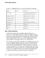
The ADSP-2192 includes a 33-MHz, 32-bit PCI interface to provide control and data paths between the device and a host CPU. The PCI interface complies with the PCI Local Bus Specification, Revision 2.2. The interface supports bus mastering as well as bus target interfaces. PCI Bus Power Management Interface Specification, Revision 1.1 is supported, and additional features needed by mini-PCI designs are included.
The ADSP-2192 has three separate configuration spaces that can be defined to support user functions by writing to the class code register for that function during bootup. Additionally, during boot time, the DSP can disable one or more of the functions. If only two functions are enabled, they will be functions zero and one. If only one function is enabled, it will be function 0.
Each function contains a complete set of registers in the predefined header region, as defined in PCI Local Bus Specification, Revision 2.2. In addition, each function contains optional registers to support PCI Bus Power Management. Registers that are unimplemented or read-only in one function are similarly defined in the other functions. Table 8-2 describes a typical configuration space.
Table 8-2. PCI Configuration Space
|
Address |
Name |
Reset |
Comments |
|
0x01-0x00 |
Vendor ID |
0x11D4 |
Writable from the DSP during initialization |
|
0x03-0x02 |
Device ID |
0x2192 |
Writable from the DSP during initialization |
|
0x05-0x04 |
Command Register |
0x0 |
Bus Master, Memory Space Capable, I/O Space Capable |
|
0x07-0x06 |
Status Register |
0x0 |
Bits enabled: Capabilities List, Fast B2B, Medium Decode |
|
0x08 |
Revision ID |
0x0 |
Writable from the DSP during initialization |
|
0x0B-0x09 |
Class Code |
0x078000 |
Writable from the DSP during initialization |
|
0x0C |
Cache Line Size |
0x0 |
Read-only |
|
0x0D |
Latency Timer |
0x0 |
|
|
0x0E |
Header Type |
0x80 |
Multifunction bit set |
|
0x0F |
BIST |
0x0 |
Unimplemented |
|
0x13-0x10 |
Base Address 1 |
0x08 |
Register Access for all ADSP-2192 Registers, Prefetchable Memory |
Table 8-2. PCI Configuration Space (Continued)
Уважаемый посетитель!
Чтобы распечатать файл, скачайте его (в формате Word).
Ссылка на скачивание - внизу страницы.