asynchronous event is expected to trigger the wake-up sequence for the DSP. The PLLOFF bit of the PLLCTL register determines the next state of the PLL after wake-up: PLLOFF=0 means the next state will be powerdown PLL mode; otherwise the next state will be Bypass mode. If the PLL was in multiply mode before it went into powerdown all mode, it will wake up in Bypass mode but will transition to multiplier mode as soon as the PLL is locked.
This chapter includes a detailed example of how to set up the programmable flags; configure the flag interrupt sources, sensitivities, and polarities; configure the interrupt priorities; and mask and enable interrupts. See “Programmable Flags Example” on page 14-54.
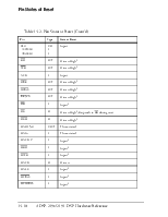
The ADSP-2191 processor has 16 general purpose flag pins, PF15-0, shown in Table 14-1 on page 14-2. Eight of these flag pins are available when the DSP is using either an 8-bit bus or a 16-bit bus; when the DSP is using an 8-bit bus, eight additional general purpose flag pins are also available. The lower eight pins (the ones that are always available) can be used in three different ways: as general purpose flag pins (referred to as PFx or PF7-0), as clock multiplier select pins (MSELx or MSEL6-0), or as select pins for external SPI devices (SPInSELx and SPISSn).
As multiplier select (MSELx) pins, these pins define the clock multiplier ratios. If the BYPASS pin is set (=1), the MSELx pins are bypassed and the clock is passed straight through to the DSP. If the BYPASS pin is cleared (=0), the values of the MSELx pins are used to determine the clock multiplier value. The DF pin (alternately named PF7) controls the input divider. The input divider is disabled when DF is cleared (=0); when DF is set (=1), CLKIN is divided by two before being used.
For information on working with the MSELx/PFx pins, see “Designing for Multiplexed Clock Pins” on page 14-38.
Data being read from a pin configured as an input is synchronized to the processor’s clock (HCLK). Pins configured as outputs drive the appropriate output value.
Using Programmable Flags
The PFx flags on the ADSP-2191 are programmed with a group of flag configuration registers: the Flag Direction register (DIR), the Flag Control registers (FLAGC and FLAGS), the Flag Interrupt Mask Registers (MASKAC, MASKAS, MASKBC, and MASKBS), the Flag Interrupt Polarity register (FSPR), and the Flag Sensitivity registers (FSSR and FSBER). These registers are described in the following sections.
Several precautions should be observed when programming these flag configuration registers:
• To avoid unwanted interrupts, software should only change a FLAGx[n] bit while its respective interrupt bit, MASKx[n], is masked.
• Five NOPs or instructions must follow an FSPRx[n] bit change, and the respective FLAG[n] bit must be cleared before its interrupt bit is unmasked.
• At reset, all flag configuration registers are initialized to zero; all flag pins are configured as level-sensitive inputs with no inversion, all flag interrupts are masked, and all interrupts are disabled.
• Narrow positive active input [n] pulses are only detectable if FSPRx[n]=0; narrow negative active input [n] pulses are only detectable if FSPRx[n]=1.
For more information about the programmable flag registers, see “ADSP-2191 DSP I/O Registers” on page B-1.
The Flag Direction register configures a flag pin as an input or output.
The DIR register is located at I/O memory page 0x06, I/O address 0x000.
(The DIR register is also aliased to I/O memory page 0x06, I/O address 0x001.) Writing a “1” to a bit of the DIR register (at either I/O address) configures the corresponding flag pin as an output; writing a “0” configures the corresponding flag pin as an input. Each bit of the DIR register corresponds with each of the 16 available flag pins of the ADSP-2191.
The Flag Control registers set or clear a flag pin.
The Flag Clear register (FLAGC) is used to clear the flag pin when it is configured as either an input or an output. FLAGC is located at I/O memory page 0x06, I/O address 0x0002. Writing a “1” to the FLAGC register clears the corresponding flag pin; writing a “0” has no effect on the value of the flag pin. The 16 bits of the FLAGC register correspond to the 16 available flag pins of the ADSP-2191.
The Flag Set register (FLAGS) is used to set the flag pin when
Уважаемый посетитель!
Чтобы распечатать файл, скачайте его (в формате Word).
Ссылка на скачивание - внизу страницы.