Alarm description |
Alarm name |
Major cause of the alarm |
Status of alarm indicator |
Default alarm level |
|
Regeneration section (B1) signal deterioration |
B1SD |
Input optical power too low or excessive error codes during transmission |
Flash once every other second |
Minor |
|
Regeneration section (B1) excessive error codes |
B1EXC |
Received signal attenuation too large |
Flash once every other second |
Minor |
The performance of RWC board include: B1 error code counting, output optical power, input optical power, laser bias current and ambient temperature.
3.1.5 Gigabit Ethernet Wavelength Conversion Unit
1. Principle
OptiX BWS 320G system is an open DWDM system, and the function of LWE board in OptiX BWS 320G system is to convert the Gigabit Ethernet optical wavelengths and make the system an open DWDM system. The client end equipment of LWE is a Gigabit router or other GE equipment. Optical signals sent from this equipment comply with IEEE 802.3Z standard. The major function of LWE board is to convert the 1.25Gbit/s optical signals within 1310 nm or 850nm wavelength range to 1.25Gbit/s optical signals of standard wavelengths in compliance with ITU-T G.692 recommendation, so that the optical signals can be multiplexed into one optical fiber.
LWE directly transmits the gigabit signals after wavelength conversion to DWDM system for transmission. In this way, the bandwidth of the optical fiber can be reasonably used and the IP transmission bandwidth in WAN can reach up to 40Gbit/s (for 32-channel system); and at the same time, the cost can be greatly reduced.
LWE can perform bi-directional optical wavelength conversion, and both the two channels adopt O/E/O mode. Its function block diagram is shown in Figure 3-6.
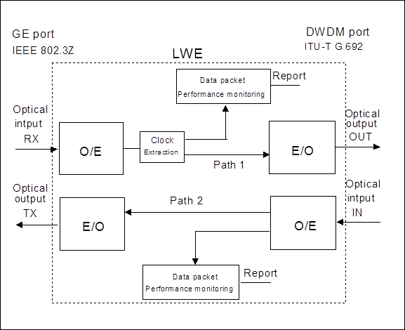
Figure 3-6 Principle block diagram of LWE board
At the input end of GE equipment, O/E conversion part of Path 1 converts the optical signals output from GE equipment with IEEE 802.3Z features into electrical signals through the photoelectric detector, and sends out GE data and clock signals after clock extraction and data recovery. Transmission packet detecting circuit detects the performance of the input signals from LWE ( such as received packet amount, received packet size, etc.) and alarms ( such receiving CRC error code frame, out-of-alignment frame, etc.). At DWDM output end, E/O part converts the received data signals into optical signals in compliance with ITU-T G.692 recommendation. This part is composed of laser, driver and modulator. The laser sends laser beams with specified wavelengths as the data signal carrier, the driver accomplishes amplification and shaping of the GE data signals to drive the modulator, while the modulator modulates the data signals to the optical carrier sent by the laser.
At DWDM input end, optical signals will suffer transmission damages to a certain extent after long distance transmission. The main transmission damages are waveform distortion and signal-noise ratio deterioration. The nonlinear effects of optical fibers, reflection of respective optical connectors, chromatic dispersion, polarization-mode dispersion, ASE noise of optical amplifier, etc. all can lead to transmission damages. In order to provide a fully transparent optical channel to GE equipment and ensure the performance of the 1.25Gbit/s optical signals during transmission, the DWDM receiving end interface of LWE is provided with a highly sensitive optical receiving module, it can reliably receive the optical signals suffered from transmission damages and send them to Gigabit router or other GE equipment from the output optical interface after reshaping and regeneration by Path 2.
2. Functions
Уважаемый посетитель!
Чтобы распечатать файл, скачайте его (в формате Word).
Ссылка на скачивание - внизу страницы.