4. Alarms and performances
Alarms and performances of WLA board are shown in Table 3-16 and Table 3-17.
3.4 Monitoring Unit
Different from SDH system, there is no access of electrical interfaces nor adding/dropping of service signals on the optical amplifier based repeater in DWDM system, only amplification of optical signals is going on. Therefore an electrical signal must be added to supervise the running status of the optical amplifier and this electrical signal must be transmitted through an additional optical supervisory channel. For the optical line amplifier adopting EDFA, the EDFA gain spectrum range is 1530~1565nm, but this range is used for the service carrier, so the carrier wavelength of this optical supervisory channel must be different from this useful gain bandwidth of EDFA, and can be added/dropped at each optical repeater--optical amplifier with sufficiently low error code rate.
According to ITU-T recommendations, the carrier wavelength adopted by the optical supervisory channel of OptiX BWS 320G system is 1510nm. Channels using this wavelength are called Optical Supervisory Channels and boards processing the channels with this wavelength is called optical supervisory channel processing board, supervisory board for short. The supervisory board is mainly engaged in the supervision of the optical channels, collection and transmission of the orderwire and NM information. According to its different location, this board can be distinguished as dual-path supervisory board at the relay station and single path supervisory board at the terminating station, named as SC2 and SC1 respectively. Transmission between the optical supervisory channel and the main channel is in WDM mode while the optical multiplex/demultiplex of the two channels are performed by the optical supervisory channel access board SCA.
3.4.1 Single Directional Optical Supervising Channel Unit
SC1 board is used to process one optical supervisory channels and accomplishes the receiving and transmitting of optical signals in the optical supervisory channels at the terminating station.
1. Principle
The principle block diagram of SC1 board is shown in Figure 3-16.

Figure 3-16 Principle block diagram of SC1 board
We'll introduce the respective functional modules based on the principle block diagram.
n Optical receiving module
The optical receiving module performs the photoelectric conversion, i.e., converts the optical signals to electrical signals for the supervisory board to process, and also sends out alarm signals when no light is received and reports to SCC board through CPU.
n Deframing circuit
The deframing circuit first performs CMI decoding of the electrical signals sent from the optical receiving module, then searches for E1 frame of CRC4 multi-frame structure from the decoded digital flow, extracts E1, E2, F1, D1~D12 bytes in E1 frame, and provides them to SCC board and overhead processing board OHP for processing; at the same time, it accomplishes E1 signal processing function, including CRC4 error code counting, remote alarm and out-of-frame alarm, etc. CPU collects such information and reports to SCC board.
E1 frame timeslot diagram adopted by the supervisory channel is shown in Figure 3-17.
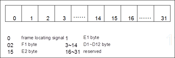
Figure 3-17 Frame structure timeslot diagram of optical supervisory channel
n Information exchange
When exchanging data with SCC or OHP board, SC1 board provides D1~D12 data channels of totally 768kbit/s. It is connected to MCF functional module of SCC board in serial mode, and provides DCC feed-through protection function when SCC is not in position as well as E1, F1 and E2 byte feed-through protection function when OHP board is not in position.
n Framing circuit
The supervisory information after information exchange of SC1 board with SCC and OHP board has to be converted into E1 data flow by CRC4 multi-frame framer, and then after CMI encoding sent to the optical transmitting module for transmission.
Уважаемый посетитель!
Чтобы распечатать файл, скачайте его (в формате Word).
Ссылка на скачивание - внизу страницы.