Note: Viewed from NM, LWE board has two paths. Path 1 is DWDM end and Path 2 is GE end.
Table 3-6 List of LWE performances
|
Performance Name |
Performance Description |
|
LSR-OUT-POWER |
Output optical power |
|
LSR-IN-POWER |
Input optical power |
|
LSBCM |
laser bias current |
|
LSCLC |
Laser cooling current |
|
RXF-OK-CNT |
Count of received correct packets |
|
RXF-CRC-CNT |
Count of received packets with CRC error |
|
RXB-OK-CNT |
Count of received correct bytes |
|
RXF-TOOLONG-CNT |
Count of received too long packets |
|
RXF-BRDOK-CNT |
Count of received broadcast packets |
|
RXF-MLTOK-CNT |
Count of received multi-cast packets |
|
RXF-PAUSE-CNT |
Count of received flow control packet numbers |
|
RXF-SHORT-OK-CNT |
Count of received correct packet with less than 64 bytes |
|
RXF-SHORT-CRC-CNT |
Count of received packets with CRC error, less than 64 bytes |
|
RXF-UNI-OK-CNT |
Count of all the correctly received unicast packets |
|
RXF-LONG-OK-CNT |
Count of the correctly received too long packets |
|
RXF-LONG-CRC-CNT |
Count of the received too long packets with CRC errors |
|
RXF-PKT-64-CNT |
Count of received packets with less than 64 bytes |
|
RXF-PKT-65-CNT |
Count of received packets with 65~127 bytes |
|
RXF-PKT-128-CNT |
Count of received packets with 128~255 bytes |
|
RXF-PKT-256-CNT |
Count of received packets with 256~511 bytes |
|
RXF-PKT-512-CNT |
Count of received packets with 512~1023 bytes |
|
RXF-PKT-1024-CNT |
Count of received packets with 1024~1518 bytes |
|
RXF-PKT-1519-CNT |
Count of received packets with 1519~max. permitted bytes |
3.1.6 STM-16 Line Wavelength Conversion unit
LWC is a line wavelength conversion board with FEC function. It combines the function of RWC and TWC together, and is added with the function of FEC(Forward Error Correction). Therefore, the equivalent sensitivity of SDH transmission system is improved, and the section distance is lengthened efficiently.
1. Principle
LWC adopts O/E/O method, and the characteristic of its output optical interface satisfies ITU-T Recommendation G.692/G.957. Its functional diagram is illustrated in Figure 3-7.
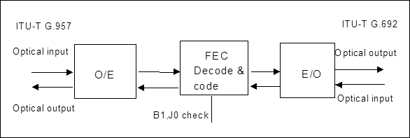
Figure 3-7 LWC Functional diagram
LWC includes transmitting OTU and receiving OTU. The transmitting OTU part firstly receives 2.5Gbit/s SDH signal by Transceiver module, and then makes FEC coding. And then the signal is output by the specified wavelength optical transmitting module, with the signal rate as 2.67Gbit/s. The receiving OTU part decodes the FEC code with rate of 2.67Gbit/s, and recovers the original 2.5Gbit/s SDH signal. And then it transmits them with Transceiver module so as to realize SDH signal transparent transmission. And besides, the corresponding performance index can be monitored during the process, such as B1,J0 bit error.
2. Functions
n Line coding type on DWDM side: Scrambled NRZ code in accordance with ITU-T Recommendation G.707;
n DWDM port optical spectrum characteristics: Maximum -20dB bandwidth is 0.2nm and minimum SMSR is 35dB;
n DWDM port nominal central frequency : 192.1~193.5THz, with the maximum central frequency deviation not more than 20GHz (within the life span)
n DWDM port minimum extinction ratio: >10dB;
n DWDM port eye pattern: as defined in Recommendation G.957.
n Optical path penalty: < 2dB;
n DWDM port minimum receiver sensitivity: -25 dBm (APD receiver module) or -18 dBm (PIN receiver module) ( on condition bit error rate BER=1.0E-12);
Уважаемый посетитель!
Чтобы распечатать файл, скачайте его (в формате Word).
Ссылка на скачивание - внизу страницы.