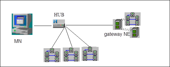
Figure 3-22 LAN connection mode
One end of a standard network cable is connected to the ethernet interface of OptiX BWS 320G NE equipment, the other end to the LAN connector; one end of another standard network cable is also connected to the LAN connector and the other end to the net card interface of OptiX BWS 320G NM terminal. In fact, most network cables at LAN side are connected to the same HUB.
(3) WAN Modem connection
Normally the transmission distance of unshielded twisted pair can reach up to 100 meters. When the NM terminal is far away from the gateway NE equipment, WAN connection mode can be adopted, then network access can be realized either by Modem dialing-up, or directly through DDN. When Modem is used, dialing mode is supported. The detailed connection is shown in Figure 3-23.
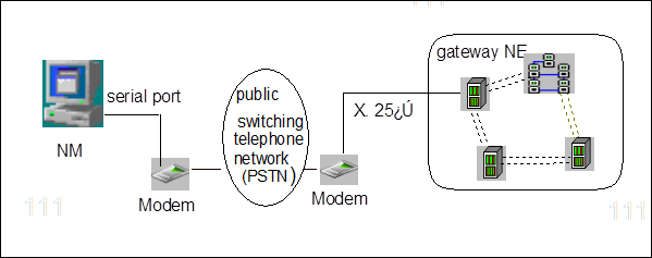
Figure 3-23 WAN Modem connection mode
Phone jacks are equipped at both OptiX BWS 320G equipment gateway NE and NM terminal. One end of Modem at gateway NE side is connected to the X.25 port of the gateway NE, while the other end is connected to the phone jack; at the NM terminal side one end of the Modem is connected to the serial port of the NM terminal, and the other end is also connected to the phone jack. And the operating system where the NM is located must be correctly installed with Modem and added with corresponding dialing network connection mode.
Needless to say, this kind of Modem WAN connection mode is advantageous in its low construction cost, but its network rate is comparatively low (the max. of 64 kbit/s) and its reliability not so high. Therefore, if condition permits, a router can be used to connect NM and remote equipment via DDN. The connection mode is shown in Figure 3-24.

Figure 3-24 WAN router connection mode
In Figure 3-24, NM terminal and gateway NE equipment are both connected to the routers through the network interfaces; while connection between the routers can be accomplished in multiple modes such as PSTN/DDN/X.25/ISDN/FR, depending mainly on the selected router type and the connection mode it can provide.
n Multiple gateway NE connection mode
NM operating system supports the connection of multiple gateways, that is to say, other NE equipment can be accessed through multiple gateway NEs. These NE equipment can be distributed in the same subnet, or located in different subnets. When not all the NE equipment are located in the same subnet, as long as the gateway NEs can be connected to the same LAN or to the same subnet through WAN, the NM terminal can still perform the management over the NE equipment of the whole network.. The connection diagram is shown in Figure 3-25.
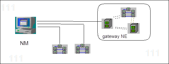
Figure 3-25 Multiple gateway NE connection mode
n Multiple NM connection mode
In this connection mode, one NE equipment is managed by multiple NM terminal systems, for example, in the telecom office, the transmission equipment is under the management of the maintenance personnel in the transmission equipment room and at the same time under the monitoring of the section chief and office director. And an NM terminal should be set at respective corresponding locations. The connection diagram is shown in Figure 3-26.
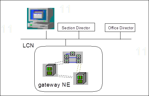
Figure 3-26 Multiple NM connection mode
n Composition of NE equipment IP address
At present, the connections between NM terminals and NE equipment are mostly in one-to-one connection mode, and the communication of the whole network is established by observing TCP/IP protocol. This requires the NE equipment to have a unique identifier--NE ID on the network so as to form its IP address identifiable by the network. Then how to set this NE physical address ID ?
Уважаемый посетитель!
Чтобы распечатать файл, скачайте его (в формате Word).
Ссылка на скачивание - внизу страницы.