3.1.7 Optical STM-16/64 Combiner Unit with FEC function.
1. Principle
When OCU board is used in OptiX BWS 320G system, in order to save the wavelength resources, 4 STM-16 signals can be converted to 1 STM-64 signal, And FEC coding is used, so the system’s ability of bearing bad environment can be greatly improved. By function, OCU board can be divided into the transmitting side and the receiving side (relative to 10Gbit/s optical interface). The transmitting side implements 4:1 function, i.e., converging 4 STM-16 into 1 STM-64. It converts the STM-64 signal into 10.66Gbit/s signal with FEC function , and transmitting. The receiving side implements the decoding of the received 10.66Gbit/s signal with FEC function, and reverts them to STM-64 signal, and then demultiplexes them to 4 STM-16 signal.
The function diagram of OCU is as shown in Figure 3-8.
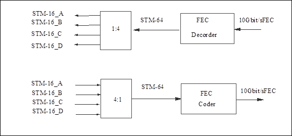
Figure 3-8 Function diagram of OCU
2. Functions
n Line coding: Scrambled NRZ code in accordance with ITU-T Recommendation G.707;
n Channel spacing: 100GHz;
n Optical spectrum characteristics: Maximum -20dB bandwidth is 0.2nm and Minimum SMSR is 35dB;
n Nominal central frequency: 192.1~195.2THz, fully meeting the requirements of ITU-T Recommendation G.692. By adopting laser wavelength stabilizing technique, the maximum deviation of central frequency is less than 10GHz (within the life span);
n Minimum extinction ratio: >10dB;
n Eye pattern: as defined in Recommendation G.957;
n Optical path penalty: < 2dB;
n The minimum receiving sensitivity of optical receiver: -18dBm (PIN receiving module) (on condition that the bit error rate BER=1.0E-12);
n Overload optical power of the receiver: -3dBm (PIN receiving module).
3. Applications
n The optical connector on OCU board handle bar is of SC type.
4. Common alarm performance
OCU board is mainly composed of the optical transmitting module and optical receiving module, so its alarms mainly reflect the working status of these two modules. Alarms of OCU board are shown in Table 3-8.
Table 3-8 List of OCU board alarms
|
Alarm description |
Alarm name |
Major cause of the alarm |
Status of alarm indicator |
Default alarm level |
|
Loss of signal at receiving side |
R-LOS |
No light input |
Continuously flash for 3 times every other second |
Critical |
|
Out of frame at receiving side |
R-OOF |
Input optical power too low or excessive error codes during transmission |
Continuously flash for 3 times every other second |
Critical |
|
Loss of frame at receiving side |
R-LOF |
Input optical power too low or excessive error codes during transmission |
Continuously flash for 3 times every other second |
Critical |
|
Laser transmitting failure |
TF |
Laser fault of this board |
Continuously flash for 3 times every other second |
Critical |
|
Laser service life will soon end |
LSR-WILL-DIE |
Laser damaged |
Continuously flash for 3 times every other second |
Critical |
|
Laser cooling current cross threshold |
LSR-COOL-ALM |
Laser damaged or ambient temperature too high |
Continuously flash for twice every other second |
Major |
|
Input power too low |
IN-PWR-LOW |
Input optical power too low |
Continuously flash 3 times every other second |
Critical |
|
Input power too high |
IN-PWR-HIGH |
Input optical power too high |
Continuously flash 3 times every other second |
Critical |
|
Transmitter deterioration |
TD |
Performance of laser deteriorates |
Continuously flash 3 times every other second |
Critical |
|
Output power too high |
OUT-PWR-HIGH |
Optical transmitting module fault or board parameter setting improper |
Continuously flash twice every other second |
Major |
|
Output power too low |
OUT-PWR-LOW |
Optical transmitting module fault or board parameter setting improper |
Continuously flash twice every other second |
Major |
|
Alarm of board not in position |
BDSTATUS |
No board in subrack slot, board mailbox fault or board not inserted properly |
Continuously flash twice every other second |
Major |
|
Regeneration section (B1) signal deterioration |
B1SD |
Input optical power too low or excessive error codes during transmission |
Flash once every other second |
Minor |
|
Regeneration section (B1) excessive error codes |
B1EXC |
Received signal attenuation too large |
Flash once every other second |
Minor |
Уважаемый посетитель!
Чтобы распечатать файл, скачайте его (в формате Word).
Ссылка на скачивание - внизу страницы.