n The co-directional data interface unit provides the physical interface for peripheral data terminal equipment. It is obvious from Figure 3-29 that it can provide a 64kbit/s co-directional interface in compliance with ITU-T G.703 recommendation.
3. Application
OHP board is always inserted in the 15th board position of OptiX BWS 320G subrack.
The main function of OHP board in OptiX BWS 320G optical transmission equipment is to provide the orderwire channels. On one hand it can provide a communication means for the engineering personnel when the optical channel is already connected through but the services are not under normal operation; on the other hand, after the services are operated normally, it can provide a communication means between the maintenance personnel of the machine rooms. In addition, it can provide a co-directional 64kbit/s data interface for the user.
Since the main function of OHP board is to support orderwire phone function, it is necessary to introduce how to set the orderwire phone numbers. There are three methods to set the orderwire phone number, with the difference in their priorities.
n The first method
Make use of the board hardware toggle switch to set the initial phone number.
Two 8-position toggle switches SW2 and SW3 on OHP board can be used to set the orderwire phone number, here we only briefly introduce several commonly used switch positions.
SW2:
D0~D3 positions are used to configure the site number ( or called the user number) of the phone number. It is defined that when the position is set to OFF, it represents 0; and when the position is set to ON, it represents 1 (same below). Suppose the configuration value is X. D4~D7 positions are used to configure the subnet number of the phone number, and suppose the configuration value is Y. Note when Y=0 or Y>9, the board will automatically set it to 1.
SW3:
When D0 and D1 are configured as 00, it stands for OptiX 155/622 old subrack, 01 for OptiX 2500+system, 10 for OptiX 155/622 new subrack; 11 for OptiX BWS 320G system. D6 position is used to configure the phone number length. "ON" represents 4 digits, and "OFF" represents 3 digits.
Now we'll give an example to see how to set the orderwire phone number with the hardware toggle switches. The composition of the orderwire phone number is as follows: subnet number + site number (user number)+ phone set serial number (fixed to 1, 2, 3). When D6 position of SW3 is set to "ON", the phone number is Y×1000+X×10+1~Y×1000+X×10+3; when D6 position of SW3 is set to "OFF", the phone number is Y×100+X×10+1~Y×100+X×10 +3. For example: the toggle switch positions of a specific site are set as follows: SW3: D0 and D6=OFF, D1=ON; SW2: D0, D1, D2 = "ON", D3 = "OFF", D4 and D5="ON", D6, D7="OFF", as shown in Figure 3-31. According to the above rules, the orderwire phone numbers of this site are 371, 372, and 373. When the setting is completed, the system, after powered on, will automatically read the toggle switch information on the board as the default phone number.
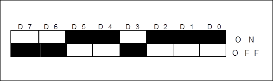
Figure 3-31 Schematic diagram of toggle switch SW2 (orderwire phone number 371, 372, 373) (shadow parts indicate toggle switch positions)
n The second method
Make use of the phone set for provisional setting.
After the orderwire phone number is set with the phone set manually, the original setting on the hardware toggle switches will become invalid. But if the equipment is powered off and then powered on again, the phone number set with the phone set will become invalid and the equipment will still automatically read the toggle switch information. Here we also only introduce some common settings:
Configure orderwire phone number: "*"+"0"+"XX…" XX…number to be configured.
Уважаемый посетитель!
Чтобы распечатать файл, скачайте его (в формате Word).
Ссылка на скачивание - внизу страницы.