At the lower left side of SCC board ( with the letters SCC on the handle bar facing upwards as a reference), there are three 4-position toggle switches, i.e., altogether 12 positions used to set the physical address of NE equipment--ID number. ID numbers must be set following certain rules. We all understand that if one physical status is to be defined by the binary system, it is either "0" or "1"; while each position of the toggle switch also only has two kinds of status: "ON" and "OFF". Here it can be defined that status "ON" represents "1" while status "OFF" represents "0". Then the different status of the 12 positions can specify a 12-digit binary number, and the value of this binary number represents the ID number of this NE equipment. For easy understanding, let's look at the following example:
Example: if the ID number of a specific NE equipment is 9, how to set the 12-digit toggle switches on its board hardware? If ID=23, how to set it?
Analysis: the 12-digit toggle switch positions are D0~D11 from low order to high order, among which D0~D3 are unit positions with the value expressed in binary system, D4~D7 are hexadecimal bits with the value also expressed in binary system. (of course D0~D7 can all be calculated in binary system and then converted into decimal system). In this example, D11~D0 positions are 000000001001 ( as shown in Figure 3-27), since ID=9, smaller than 16, D4~D11 hexadecimal positions can all be filled in with 0, and D0~D3 unit positions represent 9.
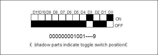
Figure 3-27 Toggle switch positions when ID=9.
When ID=23, since this value is larger than 16, and the quotient equals 1, the hexadecimal positions should be set to 1; while the remainder is 7, then the unit value should be set to 7, the D11~D0 positions of the toggle switch should be 000000010111 in sequence ( as shown in Figure 3-28 ).
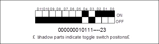
Figure 3-28 Toggle switch positions when ID=23
In fact, from the above two examples it is obvious that the decimal value of ID number can be directly converted into the binary system to get the corresponding values of toggle switch D11~D0, then the toggle switches can be set to corresponding positions according to the rule of "ON"=1 and "OFF" = 0.
4. Alarms and indicators
Common alarm types of SCC are shown in Table 3-19.
Table 3-19 common alarm types of SCC board
|
Alarm name |
Alarm description |
Alarm indicator status |
Default alarm level |
|
MAIL-ERR |
Mailbox communication error |
Flash twice every other second |
Major |
|
FAN-FAIL |
Fan failure |
Flash twice every other second |
Major |
|
WRG-BD-TYPE |
Inserted board type wrong |
Flash twice every other second |
Major |
|
VER-MISMATCH |
Version mismatch |
Flash twice every other second |
Major |
|
POWER-FAIL |
SCC board battery failure |
Flash twice every other second |
Major |
|
MEM-ERR |
Memory error |
Flash twice every other second |
Major |
|
DBMS-ERROR |
Database error |
Flash twice every other second |
Major |
Compared with the indicators on other boards, indicators on SCC handle bar have some specific characteristics as described below:
ALM (red indicator)---alarm indicator
n When the red alarm indicator is off, it means that there is no alarm occurred to the NEs managed by SCC.
n When the red alarm indicator flashes twice every other second, it means that several specific major alarms occur to the NE managed by SCC, such as: alarm signals of POWER-FAIL, FAN-FAIL, WRG-BD-TYPE, etc.
Уважаемый посетитель!
Чтобы распечатать файл, скачайте его (в формате Word).
Ссылка на скачивание - внизу страницы.