3.1.2 STM-64 Receiving Optical Wavelength Conversion Unit with FEC Function
1. Principle
The optical signal will suffer transmission damages to a certain extent after long distance transmission. In order to provide a fully transparent optical channel to SDH equipment and ensure the performance of the optical signal received by SDH optical receiver, the receiving end optical wavelength conversion boards, i.e. RWF board of OptiX BWS 320G system, adopt FEC technology and are provided with an optical receiving module of high sensitivity. It can reliably receive the optical signals that have suffered from transmission damages and send them to SDH equipment after error correcting decoding, regeneration and shaping by the repeater. Characteristics of input and output optical ports of RWF are respectively in compliance with ITU-T G.692 and ITU-T G.691 recommendations.
OptiX BWS 320G system still provides TRF board used on the electrical trunk equipment. Its receiving end has FEC decoding function and transmitting end has FEC encoding function. Refer to the introductions to TWF and RWF for the technical implementation and interface characteristics, which will not be described here.
In terms of circuit principle, RWF board, like TWF board, also adopts O/E/O mode. Its function block diagram is shown in Figure 3-3.
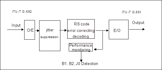
Figure 3-3 Function block diagram of RWF board
In the figure, O/E conversion part converts the error correcting encoding signal of 10.66 Gbit/s into electrical signal through the photoelectric detector, recovers the clock and extracts the data after amplitude-limited amplification, then sends 16×666Mbit/s error correcting encoding data and 666 MHz clock signal after demultiplexing.
Jitter suppression, error correcting decoding and performance monitoring parts adopt the same kernel chip with TWF board. At first, re-demultiplex 666 Mbit/s error correcting encoding signal, then complete RS decoding after a series of rather complicated algorithms. SDH signal after decoding will be demultiplexed to the performance monitoring part to monitor B1, B2 and J0. Multiple phase lock loops are adopted in the system to ensure time sequence. The decoded data enter FIFO. The data output end reads 16×622 Mbit/s error correcting encoding data with the stable clock and sends to E/O. Jitter suppression measure is adopted during this process.
The main function of E/O part is to add SDH signal to optical carrier to output. Optical transmitting module of RWF is in compliance with ITU-T G. 691 recommendation.
2. Function
n Line code pattern: in compliance with ITU-T G. 707 recommendation, being NRZ code.
n Minimum extinction ratio: > 10 dB.
n Eye pattern: in compliance with ITU-T G.691 recommendation.
n Minimum receiving sensitivity of the optical receiver: -14dBm (PIN receiving module) (under the condition of bit error rate BER =1.0E-12).
n Overload optical power of the optical receiver: 0dBm (PIN receiving module).
n Typical value of input optical signal-to-noise ratio tolerance of error code: 20dB (when error correcting function is started).
n Provide the monitoring on regeneration section B1 byte (B1 error code report, B1 cross threshold, B1 deterioration), on multiplex section B2 byte (B2 error code report, B2 cross threshold, B2 deterioration) to locate the line fault, and on regeneration section trace J0 byte.
n RWF can provide the following monitoring functions: laser bias current monitoring, laser cooling current monitoring, laser transmitting optical power monitoring and incident optical power monitoring.
n RWF has automatic laser shutdown(ALS) function.
3. Application
n RWF optical input port receives signal which is from the optical demultiplexing board and is in compliance with ITU-T G.692 recommendation, and optical output port transmits STM-64 optical signal in compliance with ITU-T G. 691 recommendation to the SDH equipment.
Уважаемый посетитель!
Чтобы распечатать файл, скачайте его (в формате Word).
Ссылка на скачивание - внизу страницы.