Performances reported by MS2 board include: optical power, central wavelength, optical signal/noise ratio.
3.7.2 Optical Line Protection Unit
1. Principle
The principle block diagram of OLP board and the optical signal flow direction are shown in Figure 3-33.
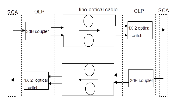
Figure 3-33 Principle block diagram of OLP board and the optical signal flow direction
OLP board is composed of the optical module and the electrical module. The optical module consists of an optical switch and a 3dB coupler. The 3dB coupler divides the output of SCA board into two paths with equal power at the optical transmitting end and transmit them into two optical line fibers. The optical switch is located at the receiving end, and its two input ports are connected to the two optical line fibers respectively to receive the signals sent from the opposite end, and then it selects one path to output to SCA board by NM control. In addition to CPU and mailbox communication circuit, the electrical module mainly consists of the driving circuit of the optical switch, which controls the switchover of the optical switch positions.
2. Functions
With the application of OLP board, optical line protection can be realized in OptiX BWS 320G system. Based on the optical power received at the receiving end, when the performance of the active optical fiber deteriorates, automatic switch to the standby fiber is implemented.
There are the following four types of OLP board switch:
n Locked switch
This function is to lock the services on the active channel fiber, no matter the active/standby channel is good or not.
n Forced switch
This function is to force the services to work in the active or standby channel fiber, no matter the active/standby channel is good or not.
n Fiber broken switch
When the services are working on the active channel fiber, if the active channel is faulty while the standby channel is normal, the services will be switched to the standby channel; if at this time the standby channel is also faulty, no switch will happen. The condition is the same if the services are originally working on the standby channel fiber.
The working mode can be set to recovery mode or non-recovery mode: in recovery mode, after the services of the active channel are switched to the standby channel, if the active channel is recovered and confirmed to be not faulty for a specific period, the services will be switched back to the active channel; in non-recovery mode, after the services of the active channel are switched to the standby channel, if the active channel is recovered, the services will still keep on the standby channel, until fault occurs to the standby channel.
n Manual switch
Since the priority of this manual switch function is lower than that of fiber broken switch, manual switch is only effective when both active and standby channels are normal. The manual switch command can be sent so that the service can be switched to either the fiber of the active channel or the fiber of the standby channel.
The relation of the above four switch functions is as follows :
The priority of the respective switch functions is in such an order from high to low as: locked switch →forced switch →fiber broken switch →manual switch. The priority principle of the protection switch function is as follows: when a specific switch function is implemented, if at this time protection switch with higher priority exists, the implementation fails; if at this time only protection switch with lower priority exists, the implementation succeeds and the protection switch with lower priority will be cleared.
Judging condition for fiber broken protection switch of OLP board is as follows:
n Pw (optical power received by the main channel) ≤-34dBm, Pp (optical power received by the protection channel) ≤-34dBm
Уважаемый посетитель!
Чтобы распечатать файл, скачайте его (в формате Word).
Ссылка на скачивание - внизу страницы.