RUN (green indicator)---running status indicator
n 100 ms on and 100 ms off means that SCC board is loading the host software.
n 500 ms on and 500 ms off means that the host software is lost and SCC board is waiting for loading the host software.
n 1 second on and 1 second off means that the SCC board is in service and in normal running status.
ETN (yellow indicator)---communication status indicator
n When the communication status indicator is off, it means that the NE equipment managed by this SCC board is not connected with the NM operating system terminal via network cables.
n When the communication status indicator flashes, it means that data transmission is going on between NE equipment managed by this SCC board and NM operating system terminal.
n When the communication status indicator is on, it means that the connection between NE equipment managed by this SCC board and NM operating system terminal is normal.
3.6 Overhead Processing Board
The overhead processing board of OptiX BWS 320G system, is abbreviated as OHP ( overhead processor). Its function in OptiX BWS 320G system is to undertake the task of inter-communication between different equipment, such as providing user channels, orderwire channels, etc.
1. Principle
The principle block diagram of OHP board is shown in Figure 3-29.
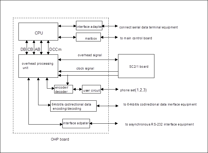
Figure 3-29 Principle block diagram of OHP board
Below, with reference to the OHP principle block diagram and its functional block composition, we'll introduce the functions of OHP.
2. Functions
According to ITU-T G.783 recommendation, the functional block composition of OHP board is shown in Figure 3-30.
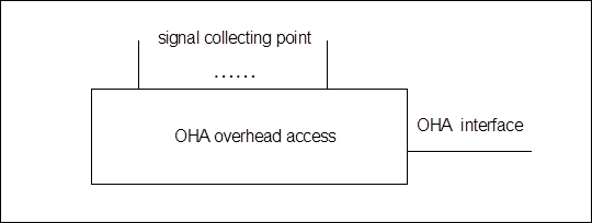
Figure 3-30 Functional block composition of OHP board
It is obvious from the diagram that the key functional block of OHP is an overhead access functional unit. Through this overhead access functional block and its interfaces, the orderwire phone and some data terminal equipment DTE ( i.e., equipment with 64kbit/s co-directional data interfaces in compliance with ITU-T G.703 recommendation and equipment with RS232 and RS422 interfaces) used for equipment running and maintenance can be accessed conveniently for OptiX BWS 320G system overhead processing.
For better understanding of the principle block diagram, the whole board can be divided into 4 parts: monitoring unit, overhead processing unit, phone set user circuit unit and 64kbit/s co-directional data interface unit.
n The monitoring unit consists of CPU and mailbox. CPU can be regarded as the control center of this board. It communicates and exchanges information with SCC board via the mailbox (dual-port RAM), including receiving the configuration data sent from SCC board and reporting the alarm information and running status of this board to the SCC board. In addition, CPU also has the ability to monitor the various status of the phone sets in this local office (such as on/off hook ) and generate corresponding operations, such as controlling the generation of dialing tone, busy tone and ringing back tone as well as the transmission of the ringing signals.
n The overhead processing unit should be regarded as the core of OHP board. It is connected to the optical supervisory channel processing board SC2 and SC1 in OptiX BWS 320G system to extract E1, E2 and F1 overhead bytes and other data bytes from the supervisory channel or add such bytes into the supervisory channel. And needless to say, its most important function is to provide three orderwire channels.
n Phone set user circuit unit communicates with the OHP via the user circuit, mainly performing the function of controlling the receiving and transmitting of system signal and supporting the normal operation of audio frequency two-wire phone sets.
Уважаемый посетитель!
Чтобы распечатать файл, скачайте его (в формате Word).
Ссылка на скачивание - внизу страницы.