Note: Either the active channel or the standby channel can report RLOS, channel 1 is the active channel and channel 2 is the standby channel.
Performances reported by OLP board include: input optical power of the active and standby channel, status of the optical switch.
3.7.3 Variable Optical Attenuator Unit
1. Principle
The variable optical attenuator can detect and adjust the optical power of the channel in real time. It is used to maintain the power value within the range and is called VOA in OptiX BWS 320G system. Automatic power control (ALC) can be realized through the coordination of VOA and optical line amplifier under the control of corresponding software.
VOA board is located between WPA board and WBA board in the optical line amplifier, as shown in Figure 3-34.
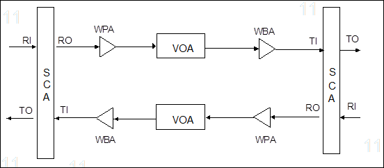
Figure 3-34 Location of VOA board in OptiX BWS 320G system
Function block diagram of VOA board is shown in Figure 3-35.
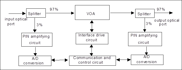
Figure 3-35 Function block diagram of VOA board
Optical module of VOA board comprises one variable optical attenuator, two demultiplexers and two optical detectors (PINs). The circuit module includes the following: the first part is the optical power detecting circuit. 3% of the detection light is demultiplexed by the demultiplexer and undergoes the photoelectric conversion, amplification and A/D conversion, then is processed by CPU. It is used to detect the input and output optical powers. The second part is the interface driving circuit of variable optical attenuator, controlling and driving the attenuator. The third part is the main control circuit, accomplishing the control, monitoring and alarm of board and the communication with the main control board SCC.
2. Function
n Automatic power control (ALC) function can be realized through the coordination of VOA and line amplifier or preamplifier under the control of NM.
Principle of ALC is shown in Figure 3-36.
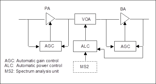
Figure 3-36 Block diagram of ALC principle
Figure 3-36 is actually the principle block diagram of line amplifier, which consists of PA, BA and VOA. PA and BA work in automatic gain control mode (AGC). Automatic power control (ALC) of amplifier is realized through the coordination of MS2 and VOA under the control of software. MS2 is a multi-channel processing unit of OptiX BWS 320G system, which can be used to analyze the count of wavelength channels in the main optical channel. It is not a part of the line amplifier, but can provide respective amplifiers with the information of channel count via NM. VOA will determine the working status and adjust the attenuation amount according to the power of output end and the wavelength channel count provided by MS2, thus maintaining the output power stable (the power of single channel remains unchanged).
n Wavelength range: 1530 ~ 1565 nm.
n Variable attenuation range: 0 ~ 15 dB.
n Resolution: 0.1 dB.
3.7.4 Dispersion Compensation Unit
1. Principle
The fiber suitable for the optical signal transmission of OptiX BWS 320G system are G. 652 and G.655, which have positive dispersion coefficient and positive dispersion slope in 1550nm window. When the optical signal is transmitted for a certain distance in the above-mentioned optical fiber, the accumulation of positive dispersion will cause the optical signal pulse to widen, thus affecting the system transmission performance seriously. The dispersion compensation module of OptiX BWS 320G system adopts the passive compensation method, using the negative dispersion inherent in dispersion compensation fiber to counteract the positive dispersion of the transmission optical fiber, thus compressing the signal pulse.
Уважаемый посетитель!
Чтобы распечатать файл, скачайте его (в формате Word).
Ссылка на скачивание - внизу страницы.