3. Application
n One SCA board can process the multipexing and demultiplexing of one optical supervisory signal and main channel, so the optical terminating station needs one SCA board while the optical relay station needs two SCA boards.
n The optical port "RI" on SCA board handle bar is the input interface of external optical signals of OptiX BWS 320G system, and it is used to receive the optical signals including the main channel and the optical supervisory channel sent from OptiX BWS 320G system; "TO" is the output port of external optical signals of OptiX BWS 320G system, and it is used to transmit the optical signals multiplexed from local main channel signals and local optical supervisory channel signals to the downstream stations; "RO" transmits the main channel optical signals to WPA or D32 or other optical demultiplexing board, and if the signals are transmitted to WPA, they have to pass through the variable optical attenuator; "TI" receives the main channel signals from WBA or M32 or other optical multiplexing boards; "RM" transmits the optical supervisory signals sent from opposite end to "RM" optical port of optical supervisory channel processing board SC1/SC2; "TM" receives the optical supervisory channel signals from "TM" port of local SC1/SC2.
n SCA can be inserted in 1~13 board positions of OptiX BWS 320G subrack.
n The optical connector on SCA board handle bar is of SC type.
n SCA board is inserted in the subrack equipped with multiplexing board.
n SCA board enables the main control board SCC to obtain the information as whether SCA board is in position by short connecting the related I/O ports of SCC.
4. Alarms and performances
Since the optical supervisory channel access board SCA is composed of one optical multiplexer and one optical demultiplexer, it is a pure passive optical device board with no electrical parts. Therefore, on SCA handle bar, there is no running and alarm indicators, nor can SCA be configured on NM. Except that the host can detect the alarm of board not in position, there is no other alarms nor performance data to be monitored.
3.5 System Control and Communication Unit
The system control and communication board of OptiX BWS 320G system is also called the SCC board, It performs the function of equipment management and communication between the equipment in OptiX BWS 320G system and provides interfaces for OptiX BWS 320G system and NM system. SCC board can be regarded as the control center of the entire OptiX BWS 320G system.
1. Principle
The principle block diagram of SCC board is shown in Figure 3-19.
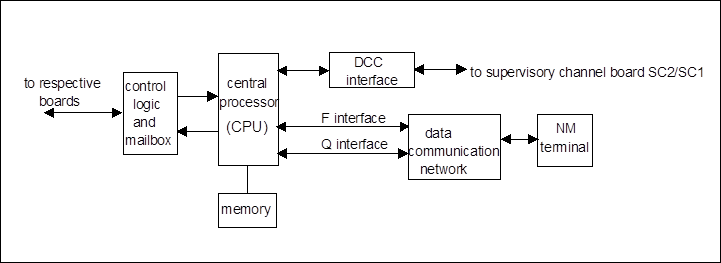
Figure 3-19 Principle block diagram of SCC board
Here, we'll introduce the functions of SCC board with reference to the SCC board principle diagram and functional block diagram.
2. Functions
According to the ITU-T G.783 recommendation, the logic functional composition of the main control unit SCC board is shown in Figure 3-20.

Figure 3-20 Functional block composition diagram of SCC board
n Synchronous equipment management function (SEMF)
The main function of SEMF is to assist the NM of OptiX BWS 320G system to perform management on respective boards and realize the monitoring, maintenance and management on the equipment in real time. SEMF functional block exchanges management information with other functional blocks through reference points, converts, processes and stores the performance data and hardware alarm events received from other functional blocks of OptiX BWS 320G system, and at the same time transmits the control and management information to other functional blocks of the equipment.
n Message communication function (MCF)
Уважаемый посетитель!
Чтобы распечатать файл, скачайте его (в формате Word).
Ссылка на скачивание - внизу страницы.