|
3.1 Optical Wavelength Conversion Unit
SDH equipment of Huawei is equipped with various optical boards of designated specifications to meet ITU-T G.692 requirements, and SDH signals can directly access the optical multiplex unit of DWDM system, thus forming an integrated DWDM system. For SDH equipment of other companies, if the performance of its line optical interface does not meet ITU-T G.692 requirements, an optical wavelength conversion unit is required to convert the optical signals that do not meet the requirement into optical signals that meet the requirement, then optical signal multiplexing is performed, thus forming an open DWDM system.
At present, OptiX BWS 320G system can provide multiple optical wavelength conversion boards: TWF board is used to convert the optical wavelength of STM-64 signals at the transmitting end, and use FEC (Forward Error Correction) technology, while RWF board is used to convert the optical wavelength of STM-64 signals at the receiving end and use the same technology as the TWF; TWC board is used to convert the optical wavelength of STM-16 signals at the transmitting end, while RWC board is used to convert the optical wavelength of STM-16 signals at the receiving end; LWE is an receiving/transmitting integrated board used for 1.25Gbit/s ethernet optical wavelength conversion. LWC combines the function of RWC and TWC together, OCU can convert 4 STM-16 signals to 1 STM-64 sign al, In the following, we'll introduce the TWF, RWF,TWC, RWC, LWE board and so on one by one.
3.1.1 STM-64 Transmitting Optical Wavelength Conversion Unit with FEC Function
1. Principle
OptiX BWS 320G system can be configured as an open DWDM system, and thus can be connected with the optical transmission equipment of any manufacturers. Through STM-64 transmitting optical wavelength conversion unit with FEC function(i.e. TWF board), OptiX BWS 320G system converts the STM-64 signal in compliance with ITU-T G.691 recommendation into the one with standard wavelength recommended in ITU-T G. 692, completing the access of signal of 10Gbit/s SDH optical transmission equipment. More importantly, in order to recover the damaged signal during the transmission, to increase equivalently the signal-to-noise ratio of optical signal at the receiving end, and to use fewer repeaters, TWF board adopts the out-of-band forward error correction technology (FEC).
To put it simply, FEC technology is a kind of error correcting encoding technology. TWF board adopts RS (Reed - Solomon) code, and it can correct up to 8 erroneous bytes in any locations among every 255 bytes, so it has strong correction capacity. Because the redundancy code is added, the data rate is increased from 9.95 Gbit/s (before coding) to 10.66 Gbit/s.
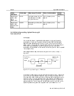
TWF adopts the O/E/O mode, the characteristics of its output optical interface are in compliance with ITU-T G. 692 recommendation, and its function block diagram is shown in Figure 3-1.
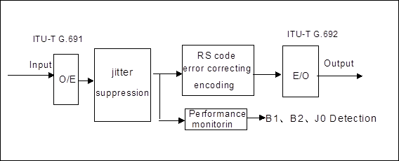
Figure 3-1 Function block diagram of TWF board
In the figure, O/E conversion part converts the STM-64 signal into electrical signal through the photoelectric detector, recovers the clock and extracts the data after amplitude-limited amplification, then sends 16×622Mbit/s SDH data and 622 MHz clock signal after demultiplexing.
Jitter suppression, error correcting encoding and performance monitoring parts are completed by adopting ASIC. At first, re-demultiplex 622 Mbit/s SDH signal, then complete RS encoding after a series of iteration algorithm. One channel of SDH signal before encoding will be demultiplexed to the performance monitoring part to monitor B1, B2 and J0 bytes. Multiple phase lock loops are adopted in the system to ensure time sequence. The encoded data enter FIFO. The data output end reads 16×666Mbit/s error correcting encoding data with the stable clock and sends to E/O. Jitter suppression measure is adopted during this process.
The main function of E/O part is to add 16×666Mbit/s error correcting encoding data signal to the optical carrier with specific wavelength and output. It is composed of multiplexer, laser, driver and modulator. The multiplexer multiplexes the error correcting encoding data of 16×666Mbit/s to 10.66Gbit/s. The laser transmits the laser with specific wavelength as the signal carrier. The drive amplifies and shapes the data signal to drive the modulator. And the modulator modulates the digital signal to the carrier transmitted by the laser.
2. Function
n Line code pattern: in compliance with ITU-T G. 707 recommendation, being NRZ code.
n Optical channel spacing: 100 GHz.
n Spectrum characteristic: maximum -20 dB bandwidth is 0.3 nm, and the minimum side-mode suppression ratio is 35 dB.
Уважаемый посетитель!
Чтобы распечатать файл, скачайте его (в формате Word).
Ссылка на скачивание - внизу страницы.