n Nominal central frequency: 192.1 ~ 195.2 THz, completely complying with ITU-T G. 692 recommendation. As shown in Figure 3-2, with the laser optical wavelength stabilization technology, the maximum frequency offset is not over 10 GHz (within the service life).
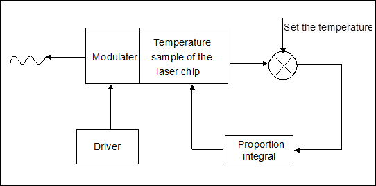
Figure 3-2 Laser optical wavelength stabilization technology
n Minimum extinction ratio: > 10 dB.
n Eye pattern: in compliance with ITU-T G. 691 recommendation.
n Optical channel cost: < 2 dB.
n Minimum receiving sensitivity of the optical receiver: -14 dBm (PIN receiving module) (under the condition of bit error rate BER = 1.0 E-12).
n Overload optical power of the optical receiver: 0 dBm (PIN receiving module).
n Error correcting encoding adopts RS (255, 239, 17) standard code to extend the transmission distance without the repeaters.
n Provide the monitoring on regeneration section B1 byte (B1 error code report, B1 over threshold, B1 deterioration), on multiplex section B2 byte (B2 error code report, B2 over threshold, B2 deterioration) to locate the line fault, and on regeneration section trace J0 byte.
n TWF provides the following monitoring functions: laser bias current monitoring, laser cooling current monitoring, laser transmitting optical power monitoring and incident optical power monitoring.
n TWF has automatic laser shutdown (ALS) function.
3. Application
n TWF optical input port receives STM-64 signal in compliance with ITU-T G.691 recommendation, and optical output port sends STM-64 optical signal in compliance with ITU-T G. 692 recommendation to optical multiplexer unit for multiplexing.
n TWF can be inserted in 1 ~ 13 board position of OptiX BWS 320G subrack.
n The optical connector on TWF board handle bar is of SC type.
4. Common alarm performance
TWF board mainly consists of optical receiving module and optical transmitting module, so its alarms mainly reflect the working status of these two modules. Alarms of TWF board are shown in Table 3-1.
Table 3-1 TWF board alarm table
|
Alarm description |
Alarm name |
Major cause of the alarm |
Status of alarm indicator |
Default alarm level |
|
Loss of signal at receiving line side |
R-LOS |
No light input |
Flash 3 times continuously every other second |
Critical |
|
Out-of-frame at receiving side |
R-OOF |
Input optical power too low or excessive error codes during transmission |
Flash 3 times continuously every other second |
Critical |
|
Loss of frame at receiving side |
R-LOF |
Input optical power too low or excessive error codes during transmission |
Flash 3 times continuously every other second |
Critical |
|
Laser transmitting failure |
TF |
Fault occurs to laser of this board |
Flash 3 times continuously every other second |
Critical |
|
Laser service life will soon end |
LSR-WILL-DIE |
Laser damaged |
Flash 3 times continuously every other second |
Critical |
|
Laser cooling current cross threshold |
LSR-COOL-ALM |
Laser damaged or ambient temperature too high |
Flash 2 times continuously every other second |
Major |
|
Input power too low |
IN-PWR-LOW |
Input optical power too low |
Flash 3 times continuously every other second |
Critical |
|
Input power too high |
IN-PWR-HIGH |
Input optical power too high |
Flash3 times continuously every other second |
Critical |
|
Transmitter deterioration |
TD |
Performance of laser deteriorates |
Flash 3 times continuously every other second |
Critical |
|
Output power too high |
OUT-PWR-HIGH |
Optical transmitting module fault or board parameter setting improper |
Flash twice continuously every other second |
Major |
|
Output power too low |
OUT-PWR-LOW |
Optical transmitting module fault or board parameter setting improper |
Flash twice continuously every other second |
Major |
|
Alarm of board not in position |
BDSTATUS |
No board in subrack slot, board mailbox fault or board not inserted properly |
Flash twice continuously every other second |
Major |
|
Regeneration section (B1) signal deterioration |
B1SD |
Input optical power too low or excessive error codes during transmission |
Flash once every other second |
Minor |
|
Regeneration section (B1) excessive error codes |
B1EXC |
Received signal attenuation too large |
Flash once every other second |
Minor |
Уважаемый посетитель!
Чтобы распечатать файл, скачайте его (в формате Word).
Ссылка на скачивание - внизу страницы.