PowerSHAPE can quickly create surfaces that are defined by a few simple parameters. These are Primitives, Extruded Surfaces and Surfaces of Revolution. The other type of surfaces which PowerSHAPE can create and edit in many flexible ways are Power surfaces.
Parameterised Surfaces or Imported, NURBS Surfaces have limited editing capability have to be converted to Power surfaces for the flexible editing.
 There are 6 primitive surfaces in PowerSHAPE, a Plane,
a Box, a Sphere, a Cylinder, a Cone and a Torus.
These primitive surfaces are generated automatically and can be a good starting
point for many models. Primitives are coloured turquoise in the pull down menu
to distinguish them from other surface options.
There are 6 primitive surfaces in PowerSHAPE, a Plane,
a Box, a Sphere, a Cylinder, a Cone and a Torus.
These primitive surfaces are generated automatically and can be a good starting
point for many models. Primitives are coloured turquoise in the pull down menu
to distinguish them from other surface options.
Each primitive, when created is given a size dependent upon the zoom of the screen. These sizes can be changed to your own values. These primitives can be moved, copied, rotated, intersected and filleted in this format. However if you want to alter the shape of a primitive surface by moving a point or adding in extra sections, it has to be converted to a Power Surface first.
With all primitives they are created in the direction of the Principal Axis. By default this is the Z-axis, so the cylinder, cone and box will stand up the Z-axis.
· Select Create New Model. ![]()
· Select the Surface menu. ![]()
· Select Plane Primitive. ![]()
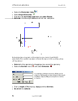
A moveable plane is attached to the cursor. The centre of the plane is this Primitive surface origin. This can be placed by picking on an item using the intelligent cursor or by typing in a co-ordinate value.
· Enter 0 in the Command input box and press Return.
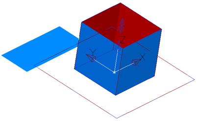
· Select the view Iso1. ![]()
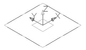
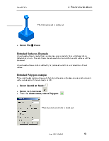
The plane is shown is position with a temporary workplane attached to it. By altering the workplane, the plane will also change.
The height and width of this plane can be dynamically dragged to the required size.
· Select the blue edge at the top of the square and dynamically pull it out to around 280.
The width can also be modified at this point using this method. If you want to be able to alter the orientation and the main features in a form then you can double click on the selected primitive to bring up the form for that primitive.
· Select the blue edge at the side of the square and dynamically pull it out to around 100.
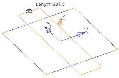
· Double click on the plane to bring up the edit form for the plane.
This form allows you to name the surface, alter the main features, width and length, reverse the surface, specify a different origin, change the orientation (Axis) and change the angle of the plane (Twist).
· Change the Width (X) to 60 and the length (Y) to 25 and press Accept.
![]()
· Press Select.
Select is used to cancel the primitive plane command, as a further click will generate another plane.
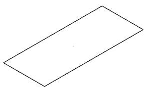
The plane looks like wireframe when it is de-selected. To see the surface clearly the shaded view is used.
· Select the Shaded View. ![]()

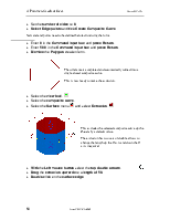
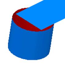
The surface can be clearly seen. The top is shaded in blue and if the view is changed then you can see the underneath is shaded red.
· Select the Surface menu. ![]()
· Select Block Primitive. ![]()
· Enter 20 -50 in the Command input box and press Return.
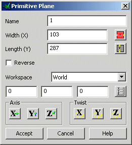
The block can be seen clearly and the surface is around the outer edges only.
The length and width can be altered by dragging the relative blue lines, but the height is altered using the double-arrow.
· Drag the length to 60 and Width to 30.
· Click on the double arrows and drag the height to 15.
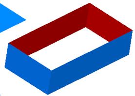
![]()
· Press Select.
The block primitive is complete. It can be selected and altered in the same way until is has been converted.
· Select the Surface menu. ![]()
· Select Cylinder Primitive. ![]()
· Enter 20 -50 in the Command input box and press Return.
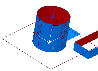
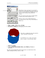
The cylinder can be seen clearly and the surface is around the outer edges only.
The radius can be altered by dragging the relative blue circles, but the height is altered using the double-arrow.
· Drag the radius to 15 and Width to 30.
· Click on the double arrows and drag the height to 25.
· Double click the cylinder to bring up the modify form.
· Select Z-Axis. ![]()
· Select Align –Z. ![]() and press Accept.
and press Accept.
· Press Accept on the Modify form.
![]()
· Press Select.
To make the cylinder length go down the Z, the primitive workplane needed to be rotated.
Уважаемый посетитель!
Чтобы распечатать файл, скачайте его (в формате Word).
Ссылка на скачивание - внизу страницы.