· Select the view Iso3. ![]()
· Select the Curve menu ![]() and
select Create a Composite Curve.
and
select Create a Composite Curve. ![]()
· Click on the top part of the bottle.
A composite curve can trace all around the curves of a surface in both directions.

· Trace around the top of the bottle until closed.
· Select Save ![]() and Eject
and Eject ![]() on the composite curve
menu.
on the composite curve
menu.
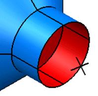
· Select the Composite Curve.
A fill-in surface is a surface that is generated from a composite curves or a series of wireframe. The surface is generated in the inner area.
· From the Surface menu ![]() select the Create
Fill in Surface.
select the Create
Fill in Surface. ![]()
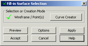
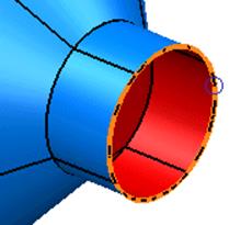
The fill-in surface form pops up and displays a preview of what the finished surface will look like.
· Press Accept. Click away to Deselect.
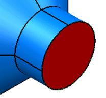
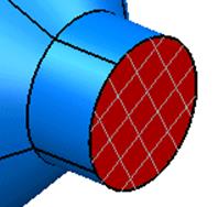
The surface has been generated. The surface is shown in red as the inside is facing towards us. This can be changed by reversing the surface.
· Select the surface with the Left mouse button.
· From the Right mouse menu select Reverse. Click away to Deselect
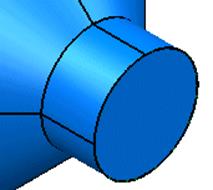
The surface has been reversed, showing the blue side, which is the outside.
· Select File è Save As and enter the name my-parameters and press Save.
By saving the model, PowerSHAPE stores the model in this state. Also it overwrites the ability to go back any further as a new marker has been set to allow you to undo back to this position.
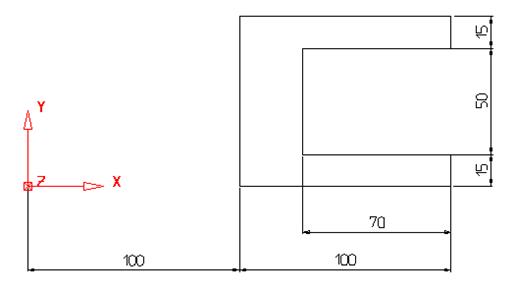
Create the following wheel shape. This will then be altered using various commands.
· Select the view from top. ![]()
· Select and Delete the two surfaces.
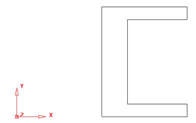
· Generate the basic wireframe shape.
· Select all the wireframe.
· Select the view Iso1 ![]() and
select the Y plane
and
select the Y plane ![]()
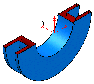
· From the Surface menu ![]() select Surface of
Revolution.
select Surface of
Revolution. ![]()
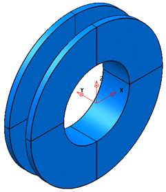
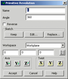
The surface of revolution is generated. The only option available to edit this surface by parameter is to change the number of degrees it spins around from the default of 180 degrees.

· Double click the surface with the left mouse button.
The primitive revolution form appears, showing the workplane options as well as the Angle.
· Change the Angle to 180 and press Accept.
The surface had been generated through an angle of 180 degrees.
To alter the physical shape of the surface of revolution the original wireframe has to be altered.
One way to alter the wireframe is to use the stretch command from the Edit toolbar.
· Click on Undo ![]() twice to return
back to the original wireframe.
twice to return
back to the original wireframe.
· Select Edit toolbar ![]()
· Select the stretch object. ![]()
·
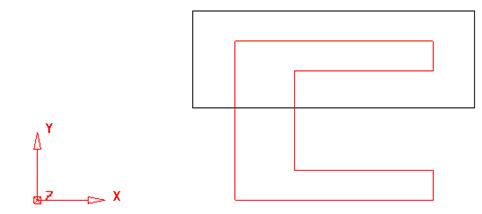 |
· Enter 0 50 which will only move the selected parts 50mm in the Y, stretching the back and inner wall.
The top half is dragged upwards and the connecting geometry is stretched.
A new surface of revolution can be made of only the inner feature by limiting the initial composite curve using the start and stop feature when tracing.
· Select the Curve menu ![]() and
select Create a Composite Curve.
and
select Create a Composite Curve. ![]()
· Select start point from the toolbar.
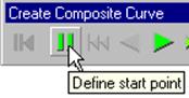
The cursor changes into two vertical bars like the Define start point icon. A circle will mark the selected start point.
· Snap this to the bottom right corner end of the wireframe.

· Select end point.
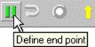
The cursor changes into two vertical bars, like the Define End point icon.
A circle will marks the selected end point.
· Snap this to the top right corner end of the model for the start point for the composite curve.
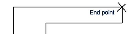
· Select the inner horizontal line.
Уважаемый посетитель!
Чтобы распечатать файл, скачайте его (в формате Word).
Ссылка на скачивание - внизу страницы.