· Enter abs 0 in the Command input box and press Return.
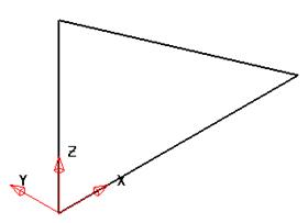
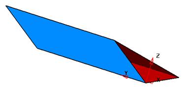
The 3D wireframe is generated. By rotating the view the geometry does not lie flat on the XY axis but is angled.
When extruding, you have the option to extrude normal to the wireframe (parallel to the wireframe) or along an Axis. This is changed via the options form.
· Select Tools è Options and then Surfaces
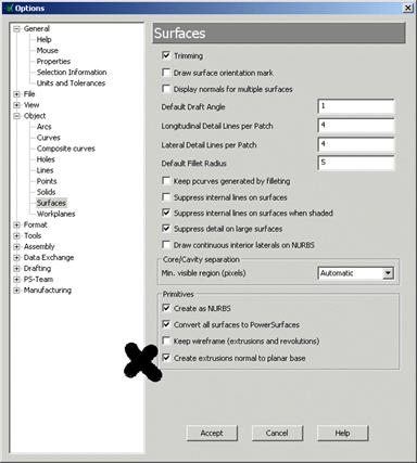
The option is Create extrusions normal to planar base.
· Tick Create extrusions normal to planar base and press Accept.
The extrusion can now be generated.
· Select all of the geometry by dragging a box over all the geometry.
· Select the Surface menu ![]() and select Extrusion.
and select Extrusion.
![]()
![]()
· Press Select.
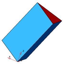
The surface is generated parallel to the wireframe and not up the Z axis. This surface will be deleted, the option changed and then recreated.
· Select Undo. ![]() .
.
· Select Tools è Options and then Surfaces
· UnTick Create extrusions normal to planar base and press Accept.
· Select all of the geometry by dragging a box over all the geometry.
· Select the Surface menu ![]() and select Extrusion.
and select Extrusion.
![]()
![]()
· Press Select.
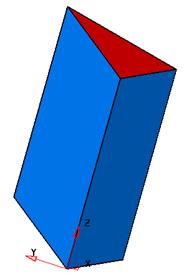
The extruded surface is now along the Z- axis. By changing the principle plane, you can extrude along different axis with the option to create normal extrusions off.
· Select Undo. ![]() . Select the Y-Axis.
. Select the Y-Axis. ![]()
· Select all of the geometry by dragging a box over all the geometry.
· Select the Surface menu ![]() and select Extrusion.
and select Extrusion.
![]()
![]()
· Press Select.
The surface is extruded along the Y axis.
· Select File è Close.
In this example an IGES file containing wireframe data is Imported into PowerSHAPE and the Surface Model will be created in stages to compliment the remaining chapters. Many different types of data formats can be imported into PowerSHAPE depending on the customer having purchased the relevant translators. Data translations can also be carried out on the Internet on a pay as you go basis through our Technical Support
.
· Select Open New Model. ![]()
· Select File and then Import.
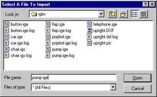
The import form appears to search for the required file.
· From E:\Users\Training\PowerSHAPE_data\iges select pump.igs and press Open.
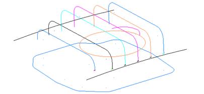
The multi-coloured wireframe appears
![]()
· Select all of the wireframe that makes the base.
· Select Z- axis ![]()
· Select the Surface menu ![]() and select Extrusion.
and select Extrusion.
![]()
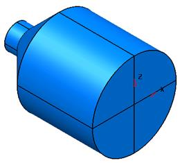
· Drag the extrusion length to 40.
![]()
· Press Select.
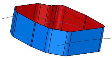
The extrusion is complete. The model must now be saved.
· Select File è Save As and enter the name pump-project2 and press Save.
· Select File è Close.
A surface of revolution is creating by revolving single geometry or a composite curve around a specified principal plane.
· Select Open New Model. ![]()
· Create a Workplane at 0 and create the bottle section geometry.
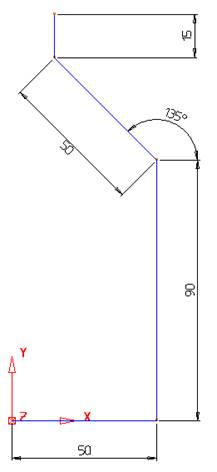
This shape will be connected together with a composite curve.
This curve will be revolved by 360 degrees around the workplane generating a surface. The correct axis for rotation around must be pre selected.
· Select the Y-Axis. ![]()
· Create a composite curve of the section geometry.
· Select the wireframe and select
the Surface menu. ![]()
· ![]() Select the Surface of Revolution
option.
Select the Surface of Revolution
option.
The desired bottle shape is produced. If a lid was required on the open end of the bottle, this can be made by capturing the end curve and using the Fill in surface command.
To capture the end curve a composite curve is traced.
Уважаемый посетитель!
Чтобы распечатать файл, скачайте его (в формате Word).
Ссылка на скачивание - внизу страницы.