· Select the Surface menu. ![]()
· Select Cone Primitive. ![]()
· Enter 20 50 in the Command input box and press Return.
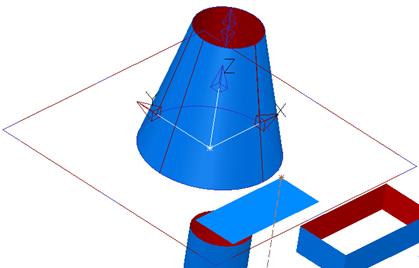
The cylinder can be seen clearly and the surface is around the outer edges only.
The bas radius and top radius can be altered by dragging the relative blue circles, but the height is altered using the double-arrow.
· Drag the base radius to 30 and top radius to 20.
· Click on the double arrows and drag the height to 40.
![]()
· Press Select.

The cone primitive is complete.
· Select the Surface menu. ![]()
· Select Sphere Primitive. ![]()
· Enter 60 in the Command input box and press Return.
With a sphere, only the radius is changed.
· Drag the radius to 20.
![]()
· Press Select.

The sphere primitive is complete.
· Select the Surface menu. ![]()
· Select Torus Primitive. ![]()
· Enter –40 30 in the Command input box and press Return.
· Drag the Major radius to 30 and the minor radius to 5.
![]()
· Press Select.
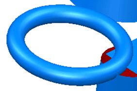
The torus primitive is complete.
· Select File è Save. Enter the name my-primitives and press Save.
· Select File è Close.
This gear stick is made up of simple primitive surfaces.
· Select Create New Model. ![]()
· Select the Workplane menu.![]() Select Single
Workplane.
Select Single
Workplane. ![]()
· Enter 0 in the Command input box and press Return.
· Select the Surface menu. ![]() Select Block
Primitive.
Select Block
Primitive. ![]()
· Enter 0 in the Command input box and press Return.
· Drag the block to be X 70, Y 70 and Z 40.
· Select Plane Primitive. ![]()
· Enter 0 0 40 in the Command input box and press Return.
· Drag the plane to be X 70 and Y 70.
· Select Cone Primitive. ![]()
· Enter 0 0 40 in the Command input box and press Return.
· Drag the base radius to 27.5, the top radius to 5 and the length to be 50.
· Select Cylinder Primitive. ![]()
· Enter 0 0 90 in the Command input box and press Return.
· Drag the length to 60 and the radius to 5
· Select Sphere Primitive. ![]()
· Enter 0 0 160 in the Command input box and press Return.
· Drag the radius to 15
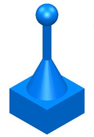
The finished model is displayed.
· Select File è Close.
An extruded surface is made from a composite curve (generally from wireframe) that is pulled along an axis. If several items are selected for extrusion then several surfaces will be generated.
An extruded surface can be modified by its parameters until it is converted into a Power surface.
This example demonstrates the use of the polygon feature to produce an octagonal extrusion with a side length of 50 and a length of 100.
· Select Open New Model. ![]()
· ![]() Select the
Line menu.
Select the
Line menu. ![]()
· From the down arrow, select Polygon.
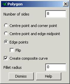
The polygon creation form is displayed.
· Set the number of sides to 8.
· Select Edge points and tick Create Composite Curve.
Start and end points need to be defined before dismissing the form.
· Enter 0 in the Command input box and press Return.
· Enter 50 0 in the Command input box and press Return.
· Dismiss the Polygon creation form.
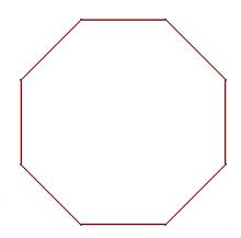
The wirefame is completed and automatically turned into a single closed composite curve.
This is now ready to make the extrusion.
· Select the view Iso1. ![]()
· Select the composite curve.
· Select the Surface menu ![]() and select Extrusion.
and select Extrusion.
![]()
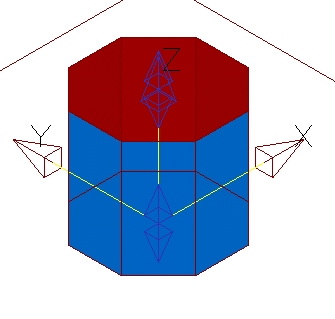
This extrudes the selected composite curve up the Z-axis by a default value.
The extrusion has two sets of double arrows to change the length up the Z axis and down the Z axis (negative)
Уважаемый посетитель!
Чтобы распечатать файл, скачайте его (в формате Word).
Ссылка на скачивание - внизу страницы.