PowerSHAPE can generate Points, Lines, Arcs, and Curves both in 2D and 3D space. These are known as wireframe entities and are used to build up certain types of Surfaces and Solids, or for use in PS-Draft, PS-Estimator or for Export to another software such as PowerMILL.
PowerSHAPE has a feature located in the line menu for producing polygons from a user specified number of sides. However this example demonstrates the manual creation of an octagon with a side length of 50 using the Position Input Form.
· Open PowerSHAPE. 
A new model is automatically opened. Wireframe geometry can now be created.
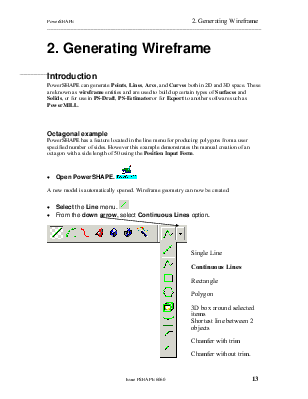
· Select the Line menu. ![]()
· ![]() From the down arrow, select Continuous
Lines option.
From the down arrow, select Continuous
Lines option.
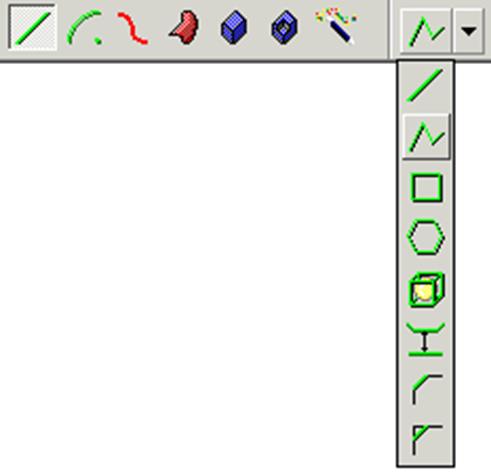

 Single Line
Continuous Lines
Rectangle
Polygon
3D box around selected items
Shortest line between 2 objects
Chamfer with trim
Chamfer without trim.
· Move your mouse around in the graphics area.
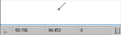 A temporary line is attached to the cursor. As the cursor is moved the
co-ordinates of the position are tracked in the XYZ co-ordinate area at
the bottom of the screen, depending upon which plane you are in.
A temporary line is attached to the cursor. As the cursor is moved the
co-ordinates of the position are tracked in the XYZ co-ordinate area at
the bottom of the screen, depending upon which plane you are in.
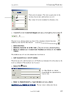
· Enter the start co-ordinate of 0 (for X0 Y0 Z0) and press Return.
![]()
This has now fixed one end of the line. As you move the cursor around the screen, an indication of the line length and angle is given. This is using the Intelligent Cursor.
A: 35 L: 49 is an angle of 35° and a line length of 49.
· Move the mouse around until you get an angle of 0° (east on a compass). (The angle indicator will disappear at this point).
· Stretch the line until it gives a line length of 50, and click with the Left mouse button.
The line will turn yellow, indicating that it is now complete. The next line automatically continues on from the end of the previous line.
· Move the mouse around to select an angle of 45°, and click the Left mouse button to finish off the line with any length.
 |
· Exit out of creation mode by selecting the Select icon.
![]()
The finished line turns yellow and has an arrow showing its direction. This line needs to be modified to be exactly 50mm long.
· Select the line with the Right mouse button. As you get nearer the line, the cursor should change into a grabbing hand.
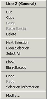
This menu is a line menu and highlights the options available. The title indicates that the item is a line and it is on the level called General, which is level 0.
The line can be Cut, Copied or Deleted from the model.
Next selection, allows picks the item underneath the line.
Blank will blank the line and Blank Except will blank everything apart from the line.
Undo, will undo the last PowerSHAPE command. Selection information will print details of the line.
Modify brings up the edit form or toolbar.
· Select Modify…
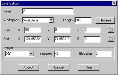
The editor form for the object type (in this case, a line) appears showing the options available.
· Change the Length to 50 and Accept the form.
TIP: Alternatively, once an object is selected, double click using the left mouse button and the relevant edit form will appear.
· ![]() Select the Line menu.
Select the Line menu. ![]()
· From the down arrow, select Continuous Line option (if not already selected).
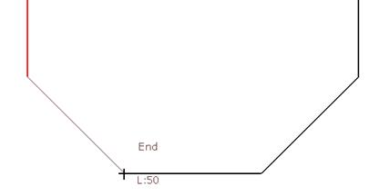
· Move the mouse towards the end of the last line. When the Intelligent cursor finds the end point the word End appears.
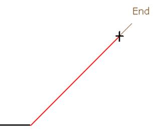
The Intelligent cursor can also find the mid-point or a distance along the line. Once the text appears, by clicking the left mouse button that will lock onto that exact position.
· Click the Left mouse button.
· Move the mouse vertically upwards until you get a distance of 50 and press the left mouse button.
The next few lines will be entered directly using the Position form.
![]()
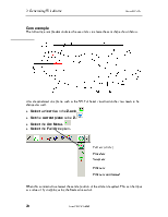
· From the bottom of the screen, select the Position input button.
The Position form appears, with the Cartesian tab selected to show Cartesian options i.e. moves in X, Y and Z.
This form has many options to enter positions.
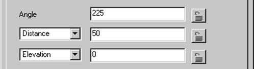
· Select the Polar tab.
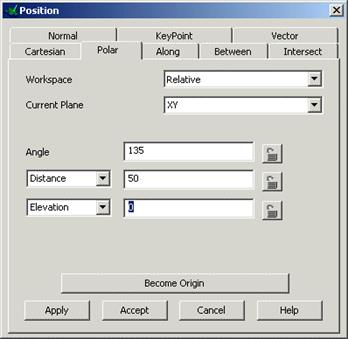
The polar tab allows angles to be defined on the current plane either from the selected position (relative) or from the world X0 Y0 Z0 position.
The Angle is the angle measured around the point, the distance is the length of the line and the Elevation is the angle that the line lifts up from the plane. If this is left as 0 a flat 2D angle is produced.
Other ways of defining a distance are covered by the other tab options.
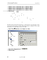
· Enter an Angle 135° and Distance of 50 and press Apply.
The line is drawn and the position form remains open until you press Accept or Cancel.
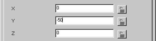
· Select the Cartesian tab in the form.
· Enter a distance of X -50 in the X ![]()
· Press Apply.
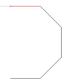
Half of the Octagon shape has been generated.
· Select the Polar tab in the form
·
 |
· Apply the form.
·
 |
· Press Accept.
· Move the cursor to the end of the first line, until the word End appears and click the Left mouse button to accept that position.
Being able to click to end points is a very useful facility.
Уважаемый посетитель!
Чтобы распечатать файл, скачайте его (в формате Word).
Ссылка на скачивание - внизу страницы.