· Select Eject. ![]()
· Select the construction line with the left mouse button.
· From the right mouse button menu, select Delete.
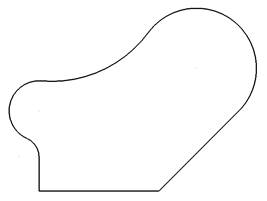
The wireframe is now complete. This can be stored onto a new level.
![]()
· From the left side of the window, select the Levels button.
· In Level 6, enter the name Hip and press the big X by the number 7.
![]()
· Select Dismiss.
· Select all the wireframe and middle mouse click over the new level 7.
The middle mouse will move the selected items to that level.
· Left mouse Click on level 7 button.
· Select File è Save.
This example goes through limiting and extending of wireframe using the commands from the Edits toolbar. The edits toolbar is not just for wireframe geometry but any selected items.
Some wireframe lines need to be generated first and these will be created using incremental and absolute co-ordinates.
· Select the Line menu. ![]()
· Select Single Lines
option. ![]()
· Enter 0 -5 in the Command input box and press Return.
· Enter 100 0 in the Command input box and press Return.
· Enter 5 –20 in the Command input box and press Return.
· Enter abs 50 50 in the Command input box and press Return.
· Enter 95 –20 in the Command input box and press Return.
· Enter abs 50 90 in the Command input box and press Return.
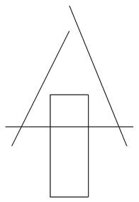
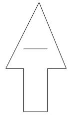
The base of the arrow is going to be created by a rectangle, which when generated is made up of four lines.
· Select the Line menu. ![]()
· Select Rectangle option. ![]()
· Enter 35 -60 in the Command input box and press Return.
This will locate the bottom left hand corner of the rectangle. Alternatively this position can be selected using the Interactive Cursor.
· Enter 30 80 in the Command input box and press Return.
· ![]() Press Select.
Press Select.
The 30 value is the actual rectangle width in X and the 80 is the rectangle height in Y.
Now the geometry is created it can be extended and limited to suit. The edit toolbar must be opened.
· From the main menu select Edits
toolbar. ![]()
![]()
The edits toolbar opens.
· Select the left angled line with the left mouse button.
· Select point limit. ![]()
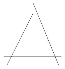
· Move the Magnet cursor to the top end of the line and when it says End click the left mouse down and drag the line up to extend until the word Intersect appears.
· Release the left mouse button.
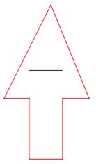
The line has been extended until it reached the other line. This command can also be used for shortening items as well.
Items that cross can be removed using the limiting command. This will trim them back to the nearest intersection.
· From the edit
toolbar, select Interactively limit. ![]()
· Move the hand cursor over the un-wanted bits and select the left mouse button.
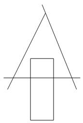
The arrow shape is now clearly defined. To put a fillet radius of 2mm on each corner, a composite curve is generated and then the fillet radius command applied.
· Hold down the ALT key on the keyboard and select one of the lines for the arrow shape with the left mouse button.
Using this shortcut ALT and left mouse button the composite curve is generated, saved and the composite curve command exited.
The fillet can now be generated.
· Select the Arc Menu. ![]()
· Select the Fillet Arc option. ![]()
· Input the value r 2 in the Command input box and press Return.
· Move the cursor over the composite curve until Fillet Composite curve appears and then Click the Left mouse button.
· ![]() Press Select.
Press Select.
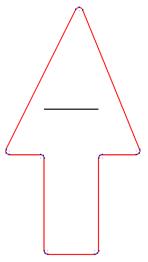
The fillets have been generated on each corner. The part can now be saved.
· Select the single horizontal line with the left mouse button.
· From the Right mouse button menu, select delete.
· Select File è Save.
· Switch on levels 5, 6 and 7.
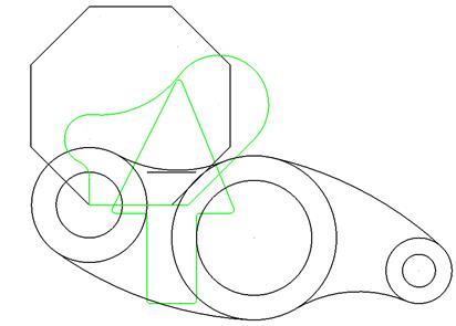
All of the geometry created on all of the levels is shown, including the arrow generated on the default level of 0.
· Select File è Exit.
· Select Yes.
Уважаемый посетитель!
Чтобы распечатать файл, скачайте его (в формате Word).
Ссылка на скачивание - внизу страницы.